Prior to operating the Rapidia Conflux 1 Furnace, please review Safety in order to avoid personal harm or damage to equipment.
¶ Software Interface
The Conflux 1 Vacuum Furnace is controlled through a touchscreen. The software user interface and its features are described in the following sections.
¶ Touchscreen Connection
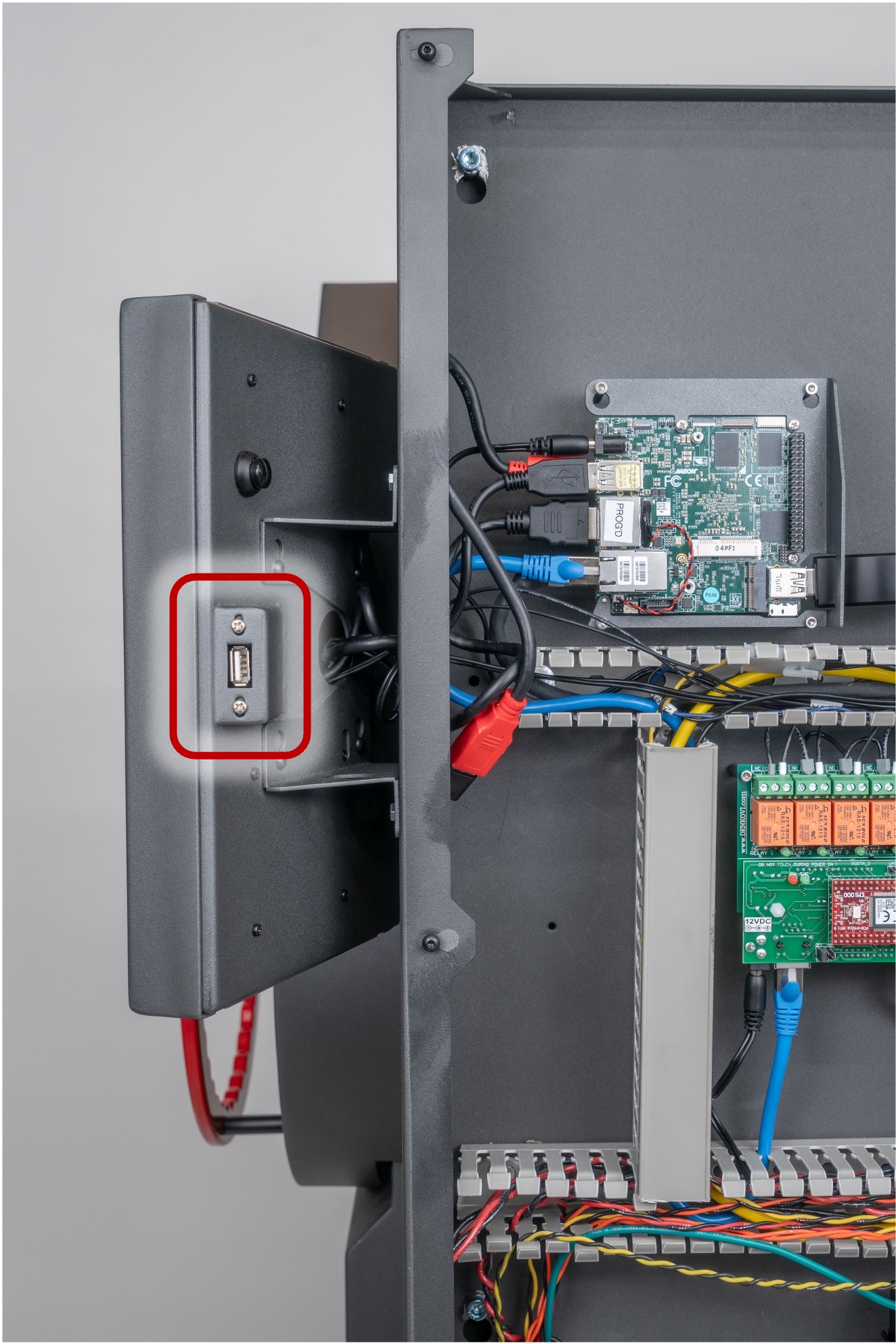
1. There is a USB port on the right side of the touchscreen as shown here.
¶ Home Screen
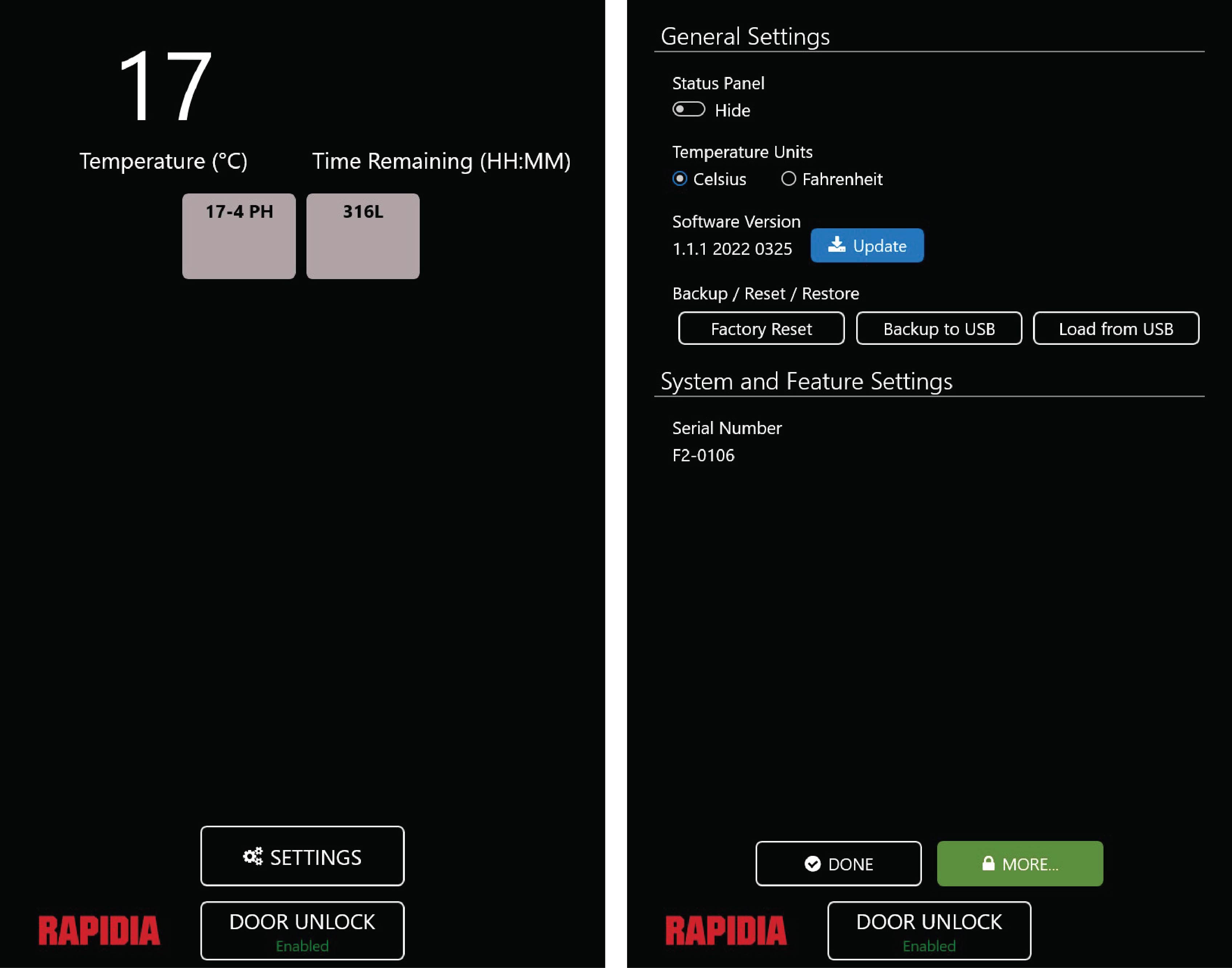
The home screen displays the furnace temperature in the top left corner, the time remaining in the top right corner, the programmed sintering cycles in the space below, and the SETTINGS and DOOR UNLOCK buttons at the bottom.
¶ Settings Screen
The settings screen, accessed by pressing the SETTING button on the home screen, is shown here. Under General Settings there are a number of functions which are described in the sections below. Under System and Feature Settings the serial number of the furnace is given. The DONE button at the bottom is used to return to the home screen. The MORE button is only used by technicians for servicing.
¶ Manual Control Using the Status Panel
1. To show/hide the status panel, use the toggle under General Settings on the settings screen, see (a). The status panel will be displayed on both the home screen and settings screen.
2. To enable/ disable manual control using the status panel, check/ uncheck the Enable Manual Control box in the bottom right corner of the screen, see (b).
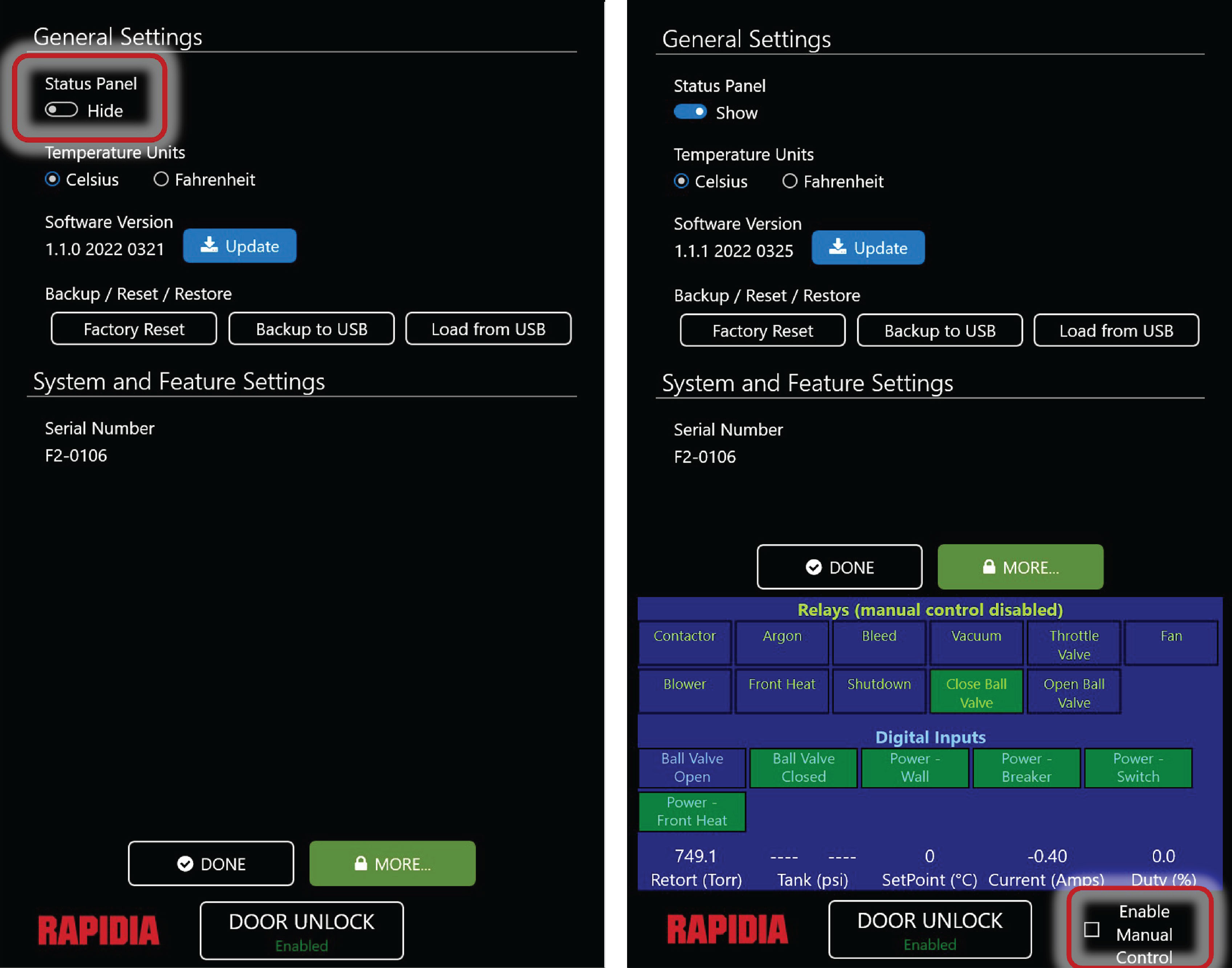
3. The bottom row of the status panel shows the retort pressure in Torr, the pressure of tank 1 and tank 2 in psi, the setpoint in °C or F, the current in amps, and the duty cycle in %.
4. The next two rows of the status panel show the digital inputs. These include whether the ball valve is open or closed, as well as the status of the wall power, breaker power, switch power, and front heat power. Green indicates ‘ON’, blue indicates ‘OFF’.
5. The top two rows of the status panel show the relays. These buttons are used to carry out several functions:
- Enable heating of the furnace (contactor)
- Switch the argon flow on/off.
- Open/ close the bleed valve.
- Turn the vacuum pump on/off.
- Activate/ deactivate the throttle valve.
- Turn the fans on/off.
- Turn the blower on/off.
- Switch the front heat on/off.
- Shutdown the furnace.
- Open/ close the ball valve.
Again, green indicates ‘ON’, blue indicates ‘OFF’.
¶ Changing Temperature Units
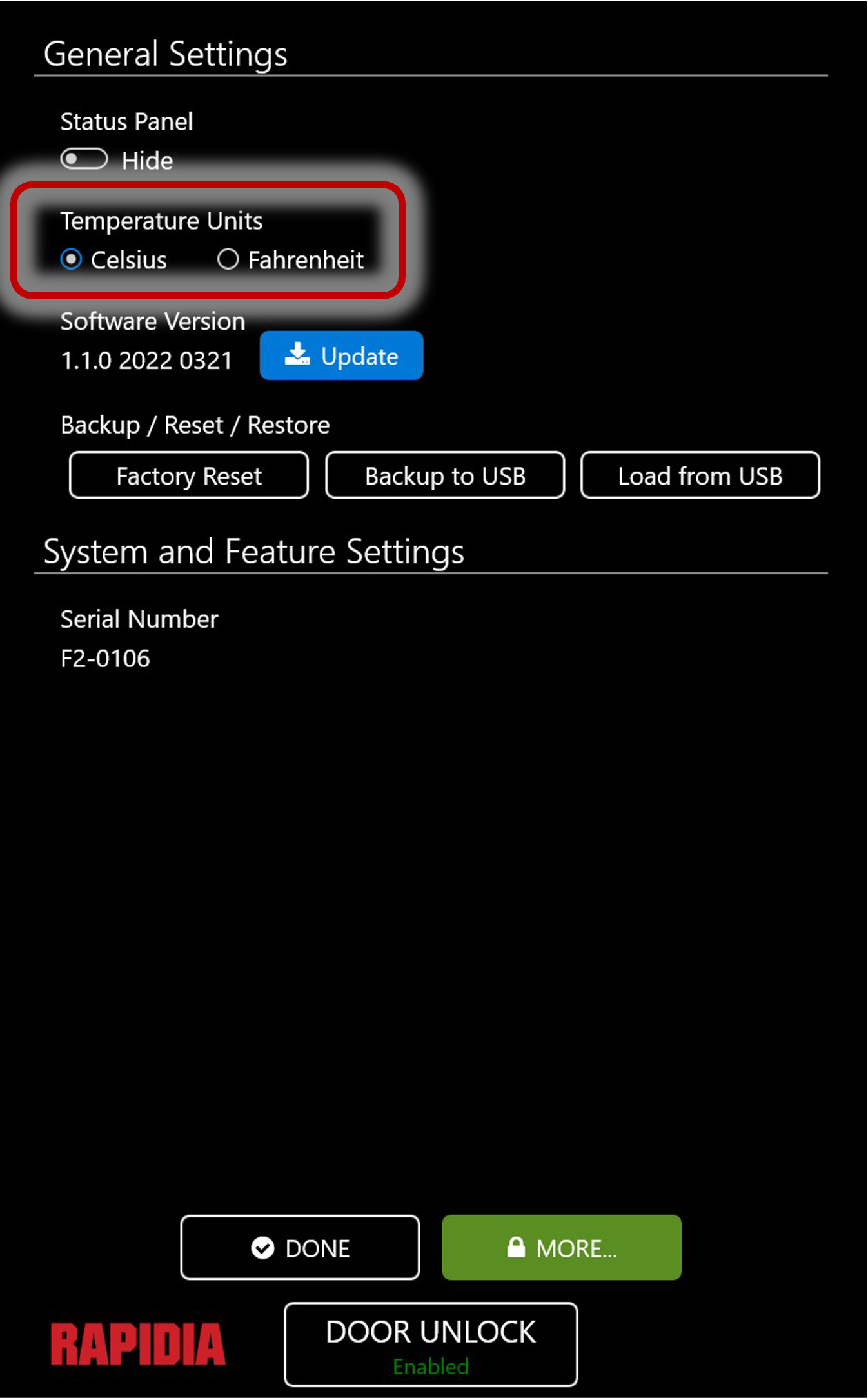
1. To change the temperature units between Celsius and Fahrenheit, use the selectors under General Settings on the settings screen, see here.
2. Obtain the latest version of the Conflux 1 Vacuum Furnace software from Rapidia. Unzip the file if applicable. Transfer the entire software update folder to the main directory of a USB flash drive (see example in (b)). Do not change the name of the folder in any way or modify any files therein; changes will result in the furnace not recognizing the correct files.
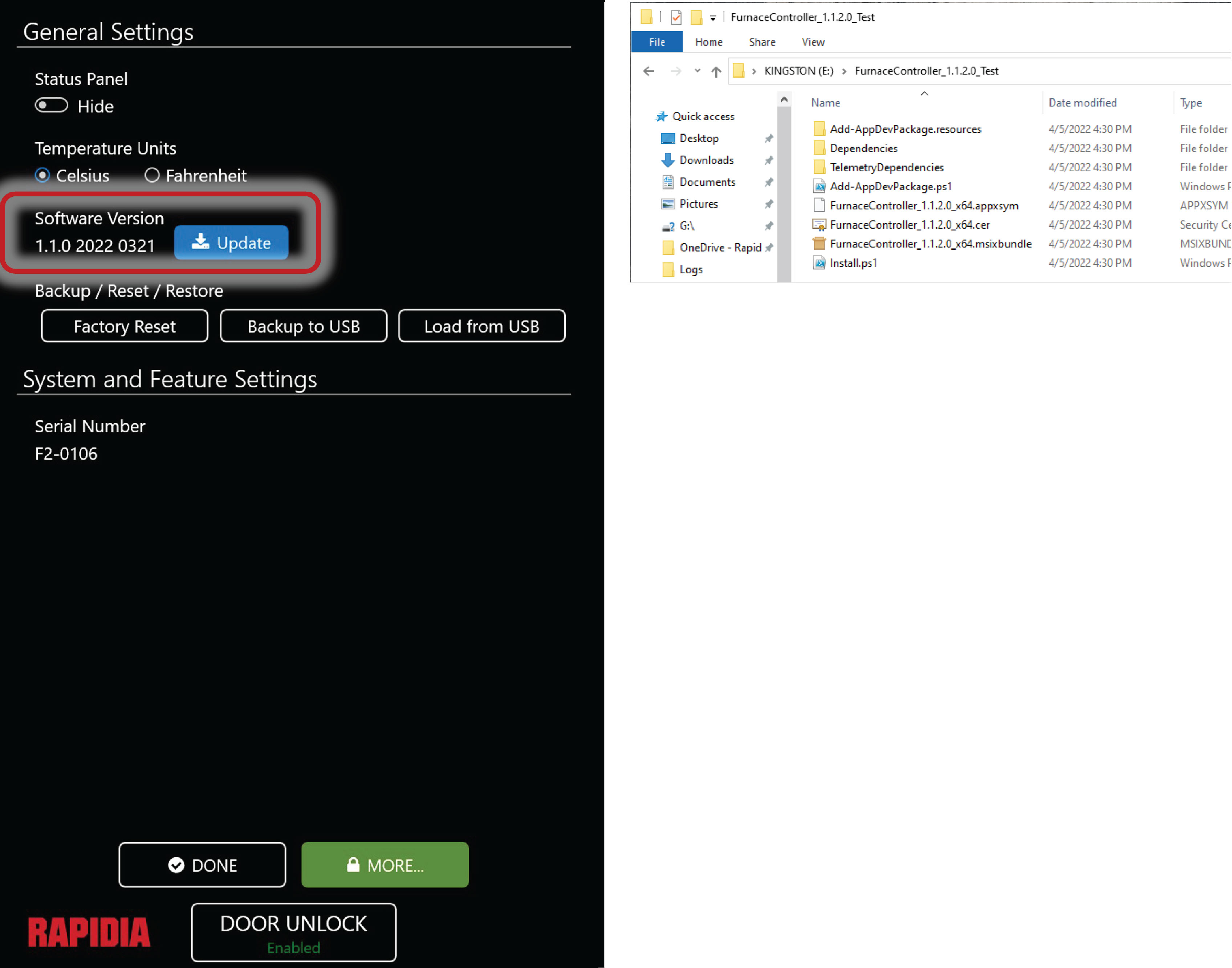
3. Insert the USB flash drive into the furnace USB port on the side of the furnace controller touchscreen.
4. Click the blue Update button under Software Version (a). The button will turn green during the update process. Once complete, the furnace will reboot.
5. Check the software version displayed under General Settings on the settings screen to confirm that the update was successful.
6. Updating the furnace software will not affect the custom cycles currently on the furnace.
¶ Backing Up To USB
1. Insert a USB flash drive into the furnace USB port on the side of the furnace controller touchscreen.
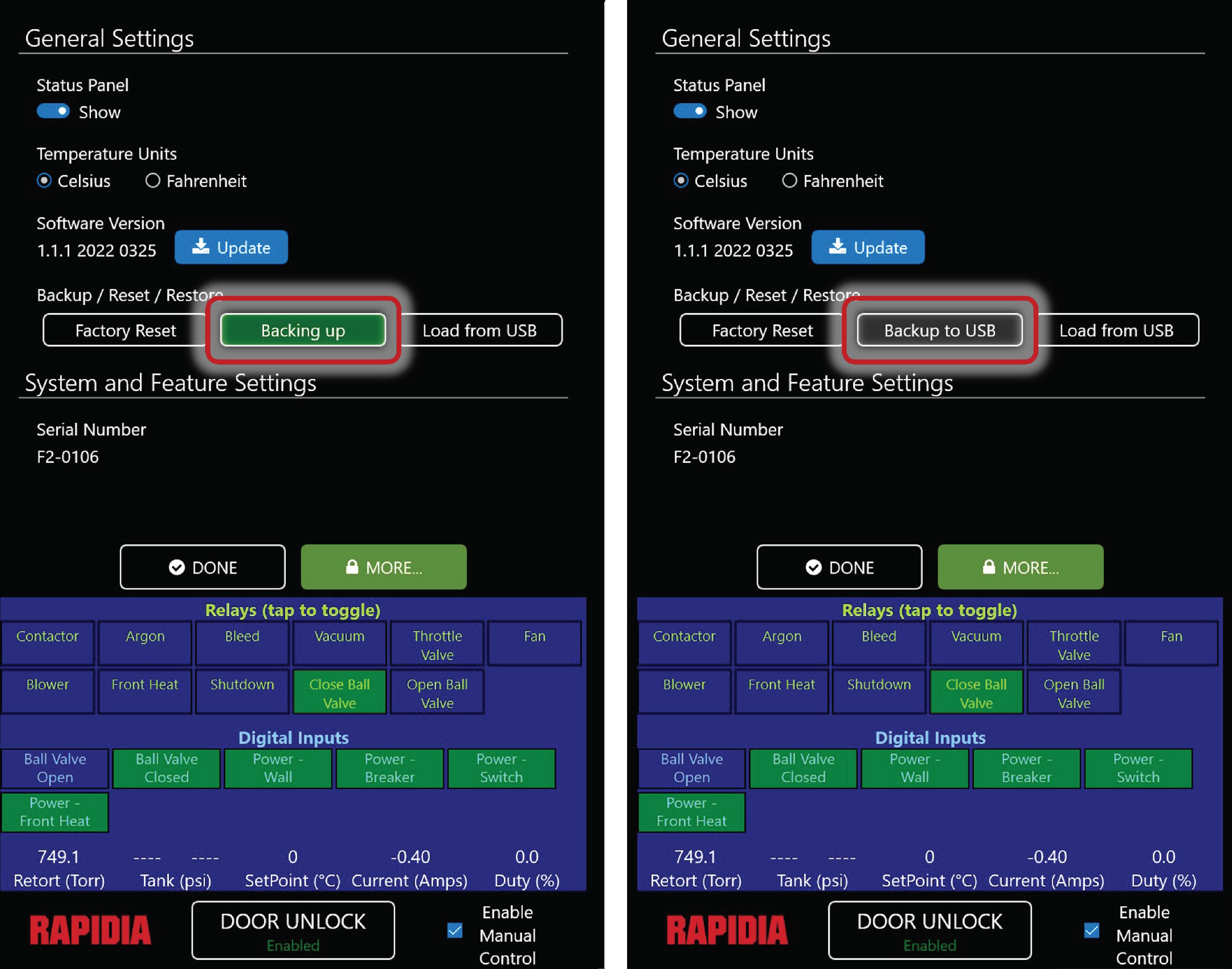
2. Click the Backup to USB button under General Settings on the settings screen. The button will turn green while backing up and then light grey when the backup is complete, as shown here.
3. Note that any existing folder named Backup on the USB will be overwritten.
¶ Retort Overview
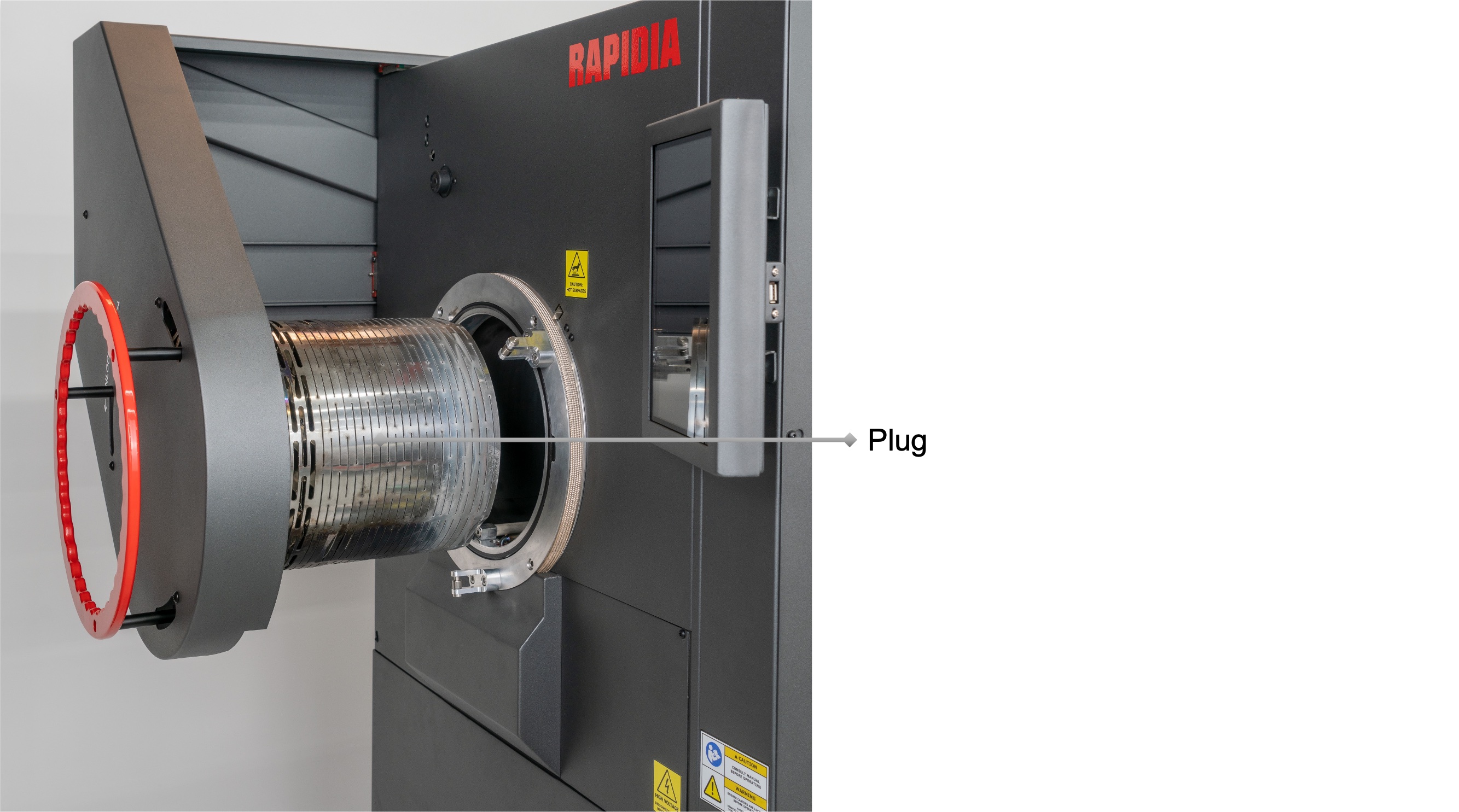
1. The retort is a 24.5 cm/ 9.65” inner diameter tube with an open front. The hot zone is in the back and the front is insulated using a baffled plug that is inserted, as illustrated in (a).
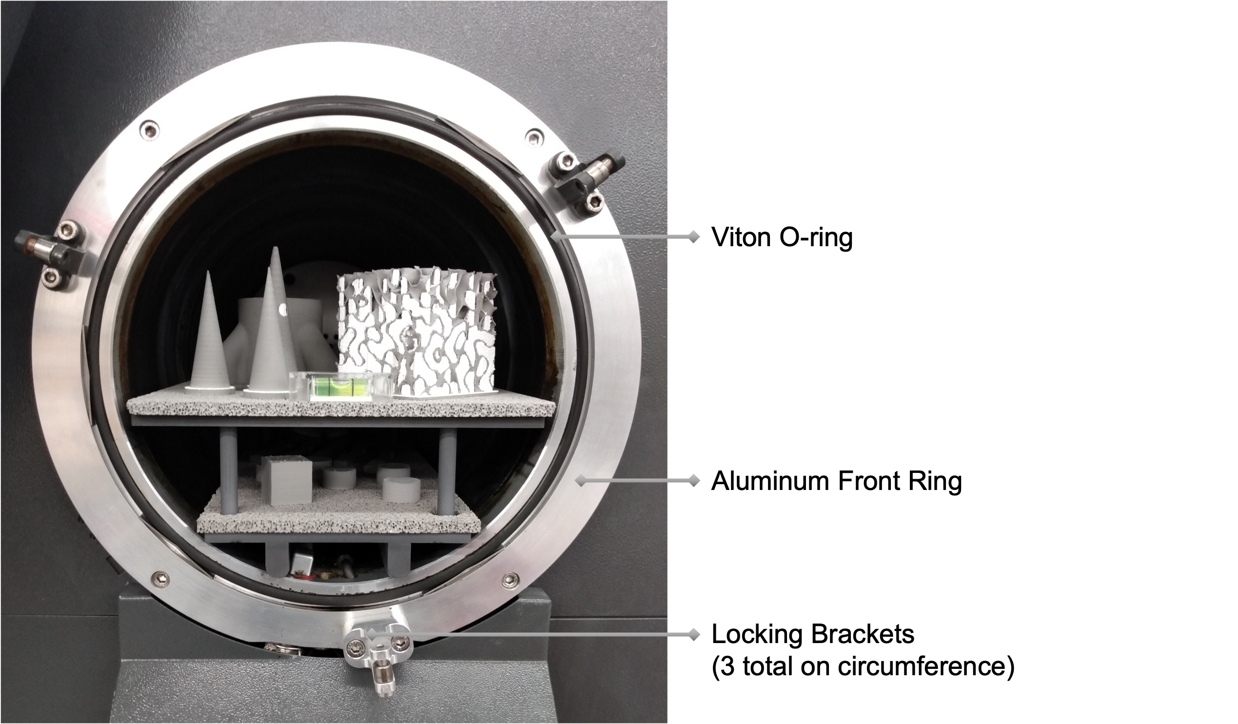
2. The viton o-ring creates a seal between the aluminum front ring and the plug. Three locking brackets are mounted on the front ring to secure the door in position. See (b).
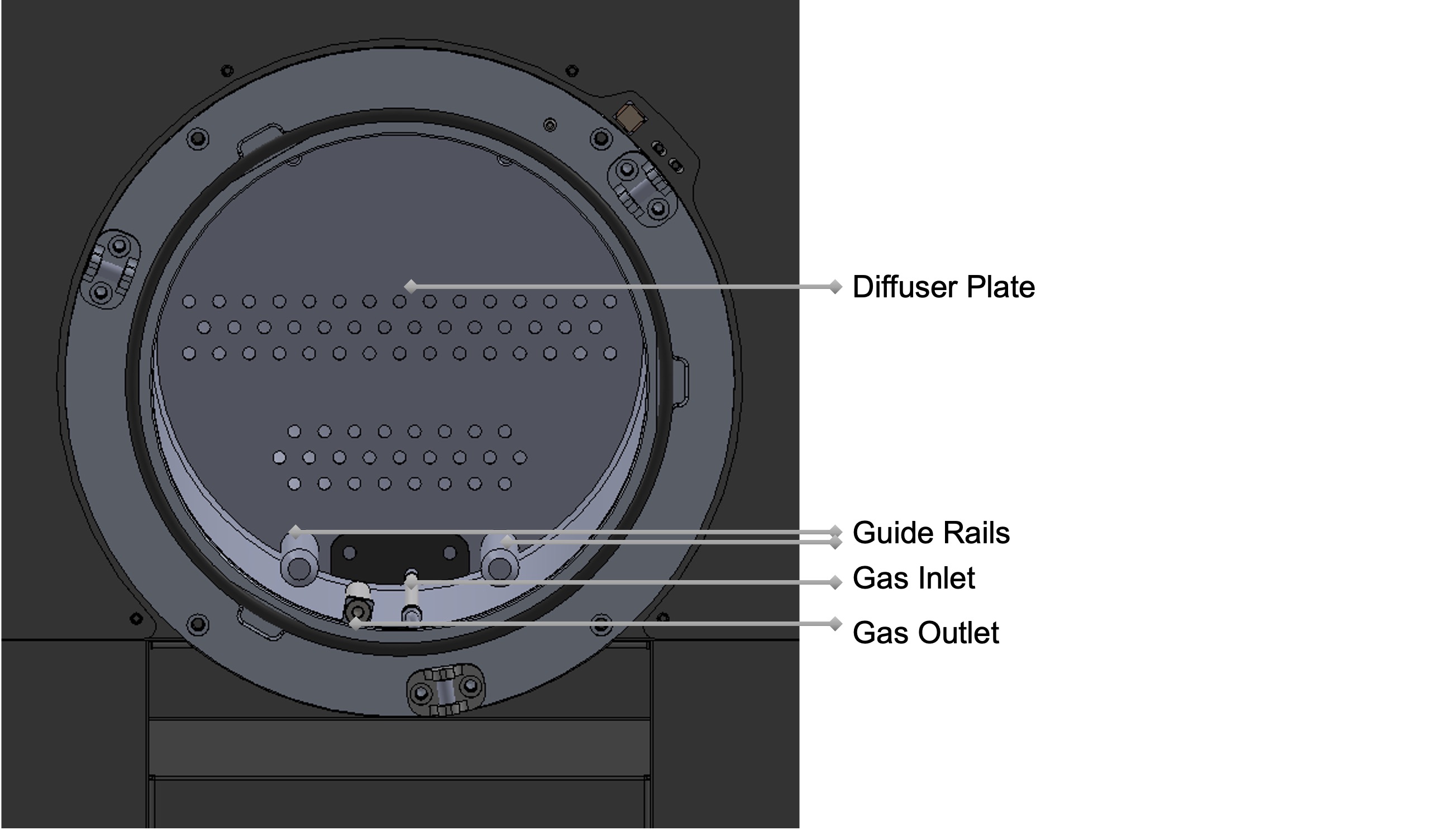
3. The interior of the retort features a gas inlet tube on the right that runs all the way to the back and releases gas behind the diffuser plate which distributes the gas flow throughout the whole cross-sectional area of the retort. The gas outlet tube runs parallel on the left side reaching to the border between the hot zone and the insulation. See (c).
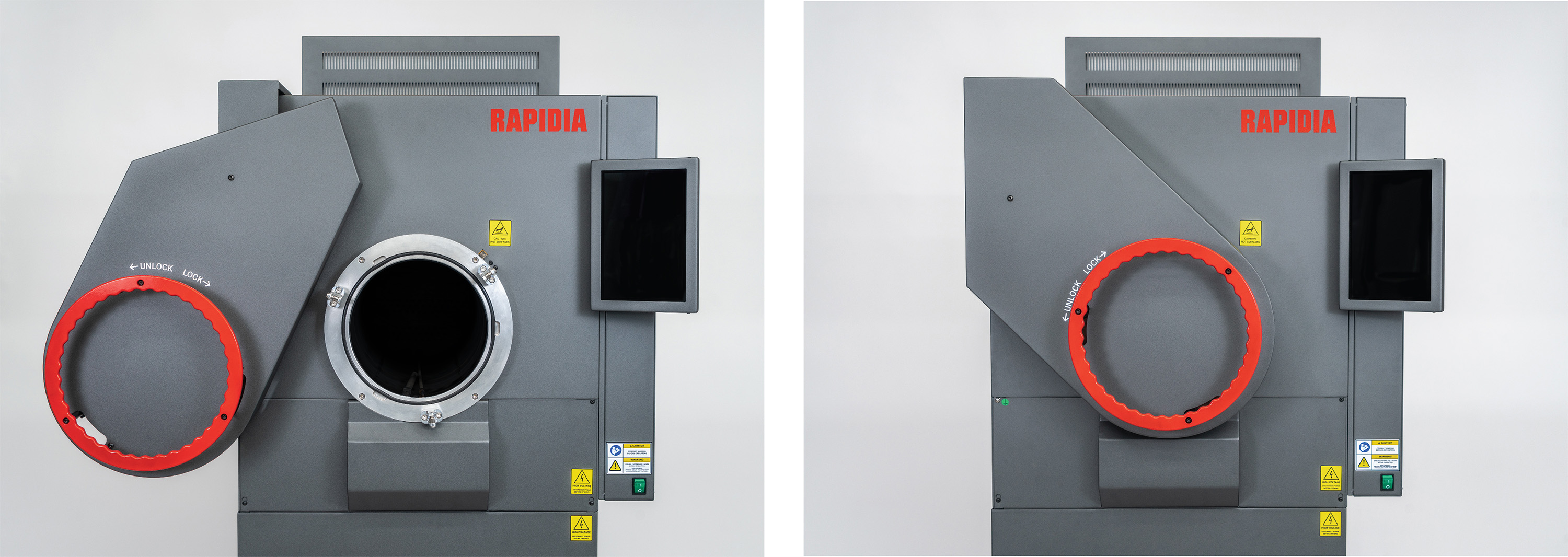
4. The retort door slides in and out parallel to the retort on a track and swings from left to right on a spring loaded hinge. From the open position (a), gently pull the door towards you as far as it will go, push it to the right against the force of the spring in a slow and controlled manner, then carefully push it forward making sure the plug is aligned with the retort and slides in smoothly. Once the door has reached the closed position (b), turn the handle clockwise to lock it. Reverse these operations to open the door again.
¶ Moving The Furnace
 |
Physical hazard: The furnace is heavy (530kg, 1170lbs). It can damage other equipment or cause physical harm when moving. Only move the furnace with 2 people or more. |
1. Do not move the furnace while a furnace cycle is running.
2. Do not move the furnace while it is hot.
3. Do not wheel the furnace across uneven surfaces. This poses a tipping hazard.
4. Move the furnace carefully in a smooth manner. Rough movements and excessive vibrations may damage the heating elements and/or other furnace components.
5. The furnace sits on 4 casters.
a. The locked position is shown in (a). Turn clockwise to unlock.
b. The unlocked position is shown (b). Turn counterclockwise to lock.
6. When stationary and in operation, all four casters should be fully locked.
7. Before moving the furnace, unlock all four casters. Then carefully move the furnace with at least 2 people.

¶ Tray Selection and Assembly
1. Determine whether the two shelf or single shelf configuration is more suitable based on the number and dimensions of the green parts. See Part Sintering Configurations for details.
2. Two shelf configuration assembly:
- Gently screw the 4 support pegs into the bottom tray to hand tightness. Careful: overtightening may damage the threads. See (a).
- Place the corresponding setter plate on the smaller bottom tray. See (b).
- Place the corresponding setter plate on the larger top tray. See (c,d).
- The trays will be stacked inside the retort once parts have been placed on them Loading The Trays Into The Retort.

3. Single shelf configuration assembly: Place the corresponding setter plate on the smaller bottom tray (same as above).
¶ Preparing Parts For Sintering
 |
Respiratory hazard: Handling green parts, especially while sanding, may release fine metal powder. Wear a respirator to prevent inhalation. |
To prepare green parts for sintering:
1. Ensure that the parts are thoroughly dried and no wet spots remain. For large parts with solid infill, additional drying in a heated convection oven may be required after completing a print to reach full dryness.
2. Perform any desired post-printing operations such as water bonding and/or sanding and smoothing. Please refer to the Printer Manual for instructions on these operations.
¶ Positioning Parts On The Trays
 |
Note: if parts contact the graphite support plates or the tube itself, they will form an alloy. This can lead to failure of the tube and all the parts in the sintering run. Take care to position parts such that they will not roll off of the shelves or collapse onto them in the case of thin parts that may deform or crack during processing. For example, do not place cylindrical parts on their side on the cylindrical surface in a way that they may roll. |
Once parts have been prepared for sintering according to Section 5.5, follow these steps to position them on the trays:
1. Clean off residue previously accumulated on any of the shelves and setter plates. Compressed air is recommended for this, gentle use of a stainless steel scraper only if necessary. Avoid any wet cleaning methods or cleaning tools that could leave residue (i.e., brush that sheds bristles, cloth that loses fibers, etc.).
2. Place the alumina setter plates onto the graphite shelves aligning the two parts (see here).
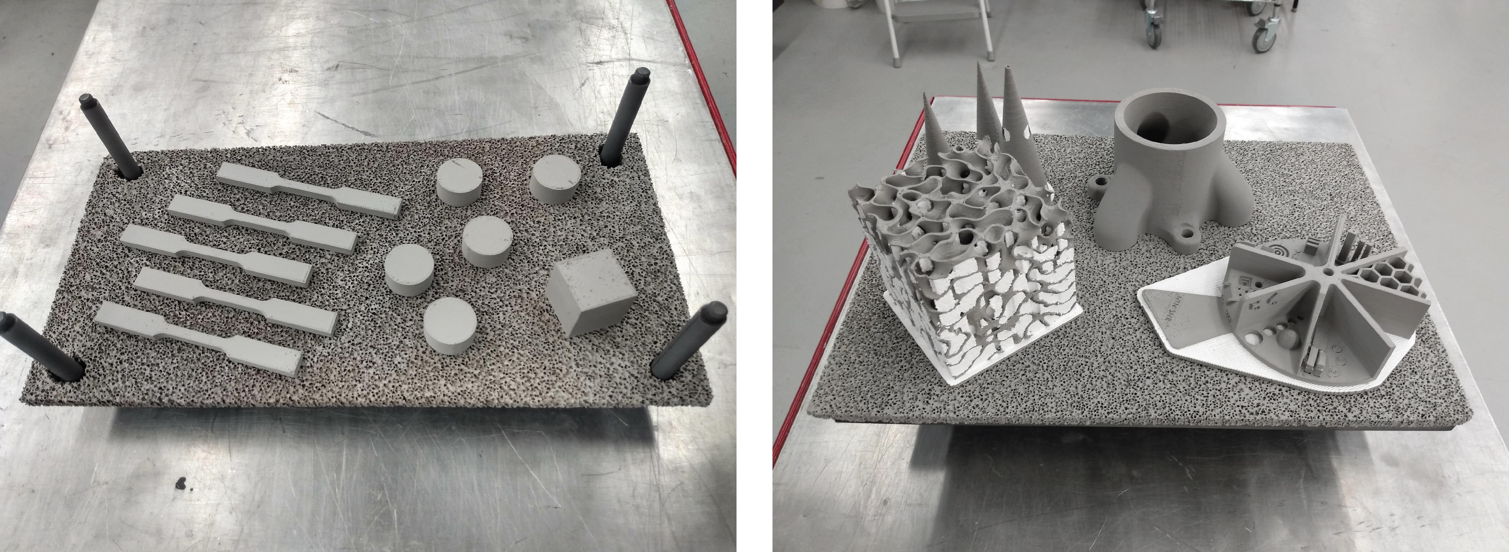
3. Position green parts onto the sintering tray one by one to achieve the most efficient layout. Keep a minimum of 5 mm between parts and keep at least 5 mm of space clear from the edge. When sintering parts of different heights in the same run, place shorter parts further upstream to the gas flow (closer to the diffuser plate). Remember that the top shelf can accommodate taller parts.
¶ Loading The Trays Into The Retort
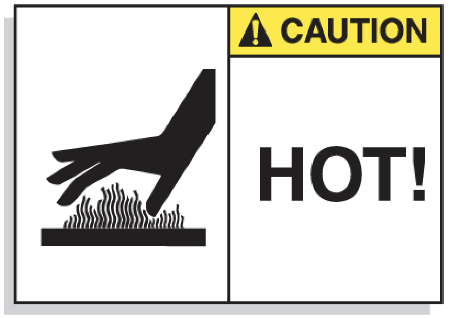 |
Burn hazard: Depending on time elapsed since the previous cycle ended, components of the retort assembly can be very hot. Wear forearm length heat resistant gloves to prevent burns. |
Once the parts have been positioned onto the tray, it can be loaded into the retort as described below.
1. Before proceeding, perform the following checks:
- Check that the diffuser plate in the back of the furnace is standing upright (see Retort Overview). Bad positioning of the diffuser plate may lead to non-uniform gas flow.
- Briefly clean out any residue left behind from the previous run (see Cleaning the Furnace Retort). Significant amounts of accumulated residue may affect sintered part properties.
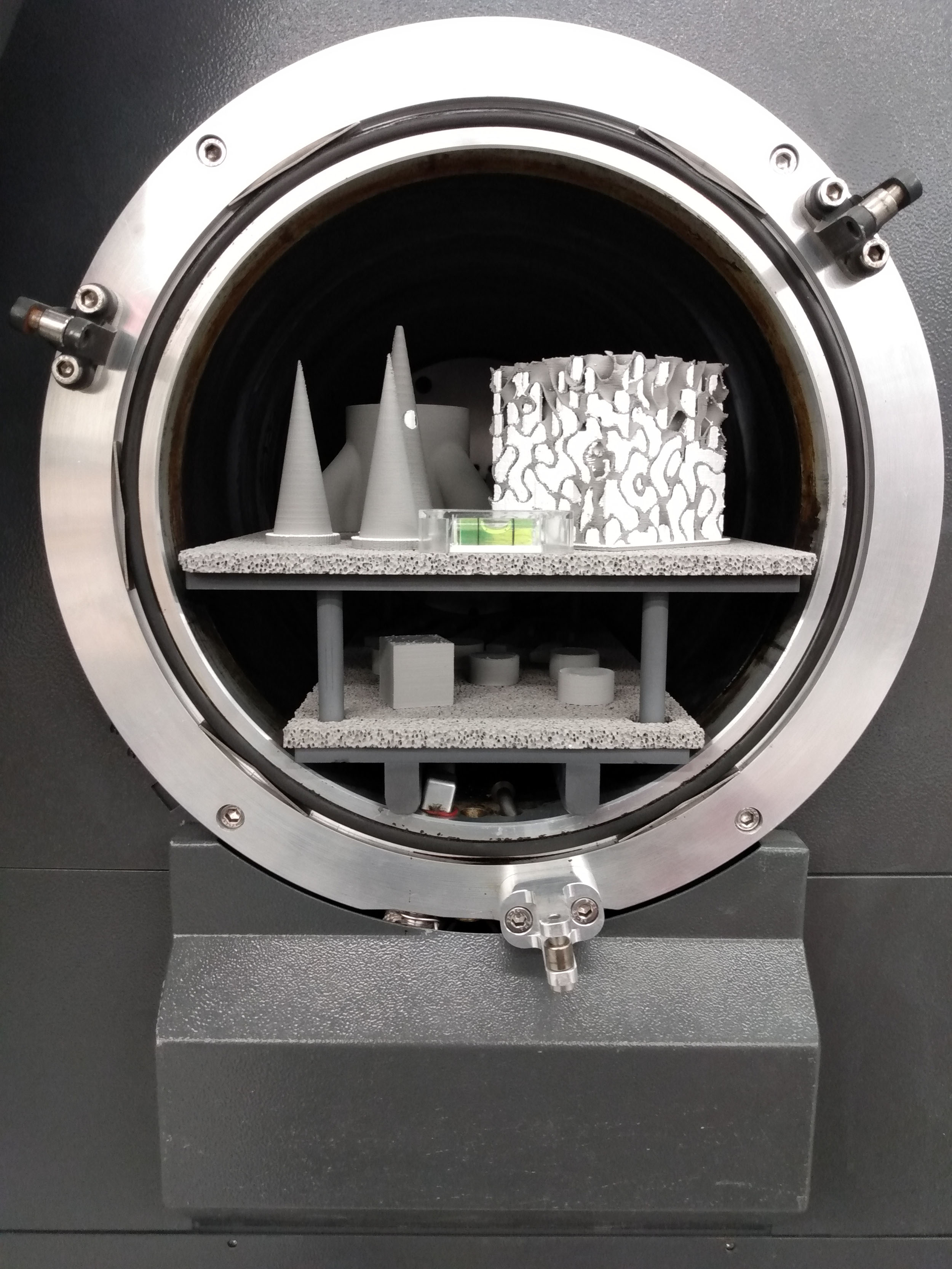
2. Two shelf configuration:
- Place the bottom tray into the retort, flush with the front ring.
- Position the top tray onto the support pegs, lined up with the bottom shelf. See (a). When sintering particularly tall parts, be careful not to hit the top of the furnace tube. Clean off any powder that may get on the walls during loading.
- Carefully slide both trays towards the back of the retort until it just about touches the diffuser plate.
3. Single shelf configuration:
- Place the bottom tray into the retort, flush with the front ring. When sintering particularly tall parts, be careful not to hit the top of the furnace tube. Clean off any powder that may get on the walls during loading.
- Carefully slide the tray towards the back of the retort until it just about touches the diffuser plate.
4. Take one last look at the shelves to ensure there are not parts touching graphite or at risk of falling over or rolling off the shelves - see note above for more detail.
5. Once the shelves have been properly positioned in the back of the retort, check that the viton o-ring on the front ring sits uniformly in its groove, then close and lock the door (see Retort Overview).
¶ Running A Furnace Cycle
After parts have been loaded on the trays, positioned in the retort, and the door has been locked, proceed to start the furnace cycle using the touchscreen interface:
1. Navigate to the home screen which displays the available furnace cycles and select the appropriate cycle for the material to be sintered from the touch screen (a). The time required for the cycle will be displayed in the top right corner. The type of cycle selected and job name is shown in the row below. If there is not enough gas available for the run, the status indicator in the middle of the screen will read “Insufficient Sintering Gas” in red. Otherwise, the status panel will read “Ready” in green. See (b).
2. Click the green RUN button to start the cycle. See (b).
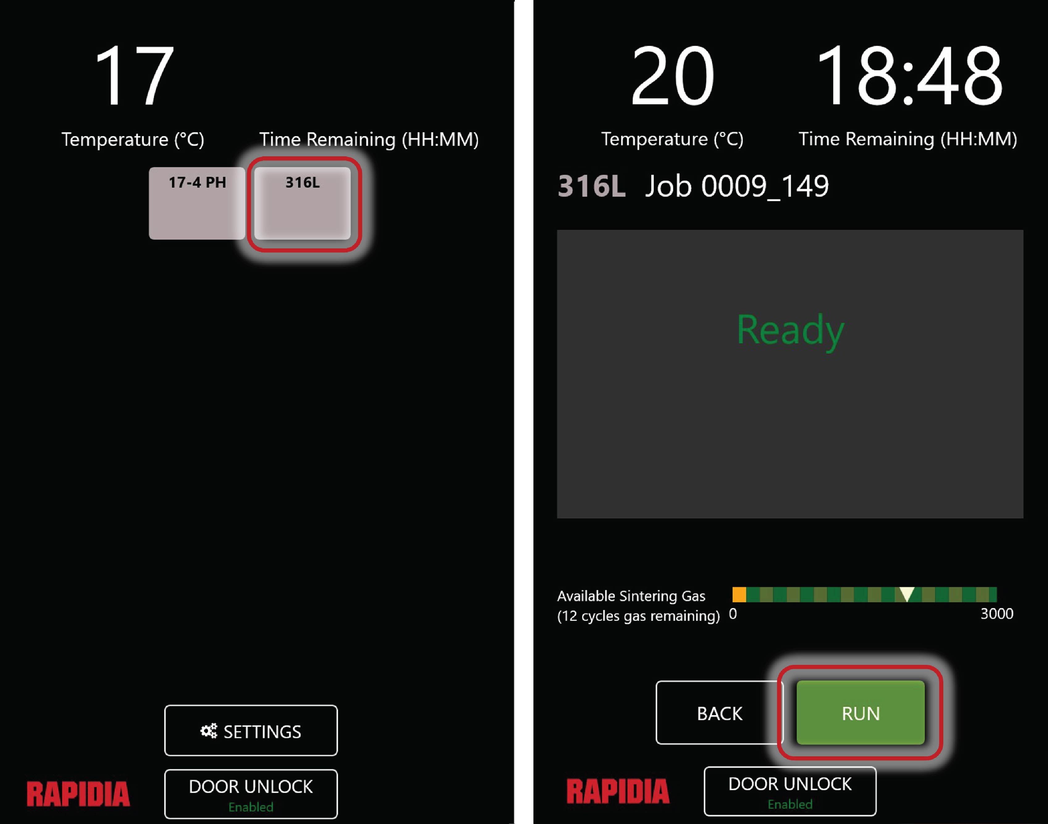
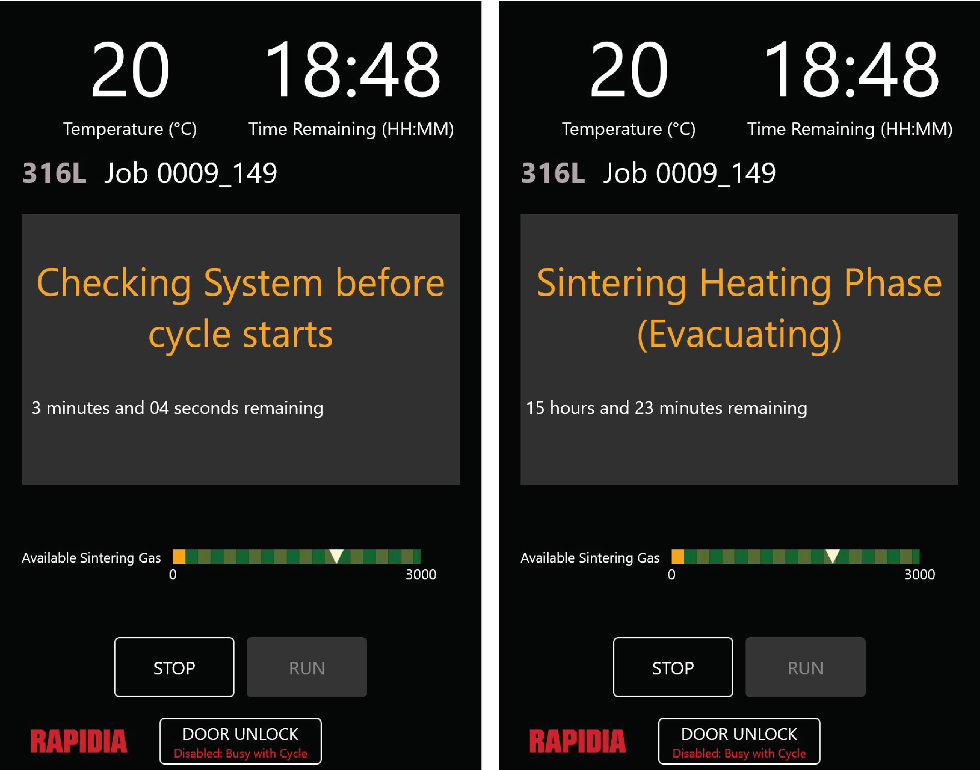
3. Before starting the cycle, the furnace will perform a self-check which takes about 3 minutes. See (a). The self-check determines whether the following conditions are met:
- The system pumps down to a low enough pressure.
- The leak up rate is low enough.
- The pressure is effectively regulated by the vacuum pressure control valve.
- The front fans are working properly.
- There is sufficient sintering gas
- The flow rate is approximately correct
4. The user should check that the self-check has succeeded. If there is an error message, refer to Troubleshooting to address the issue.
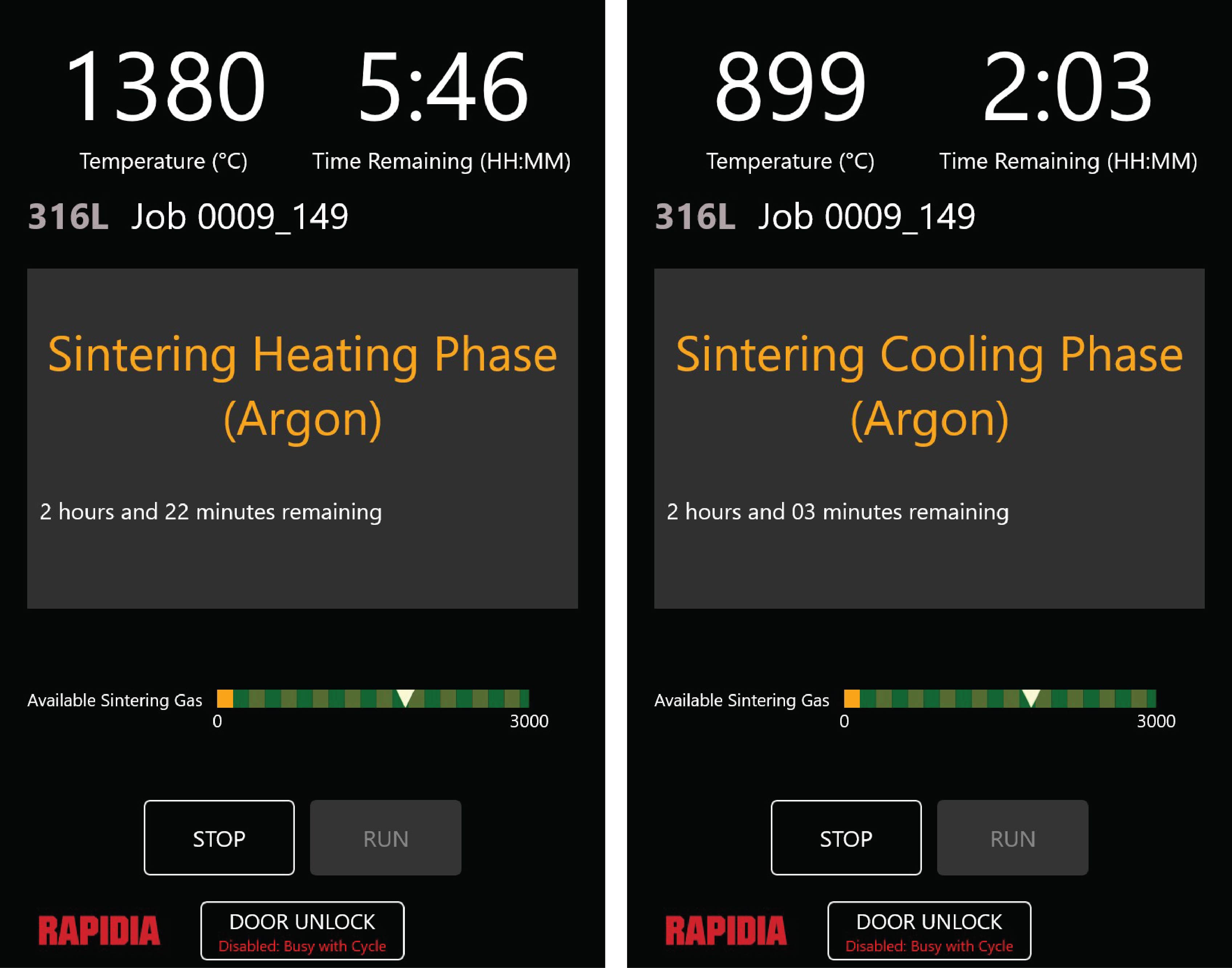
5. Once the cycle is running, the Door Unlock button will be disabled, the STOP button is active while the RUN button is inactive, and the following info is displayed:
- Temperature in °C or F.
- Time remaining in HH:MM.
- Name of cycle and job ID.
- Phase of cycle.
- Time remaining for current phase of cycle.
- Available sintering gas scale.
See (b).
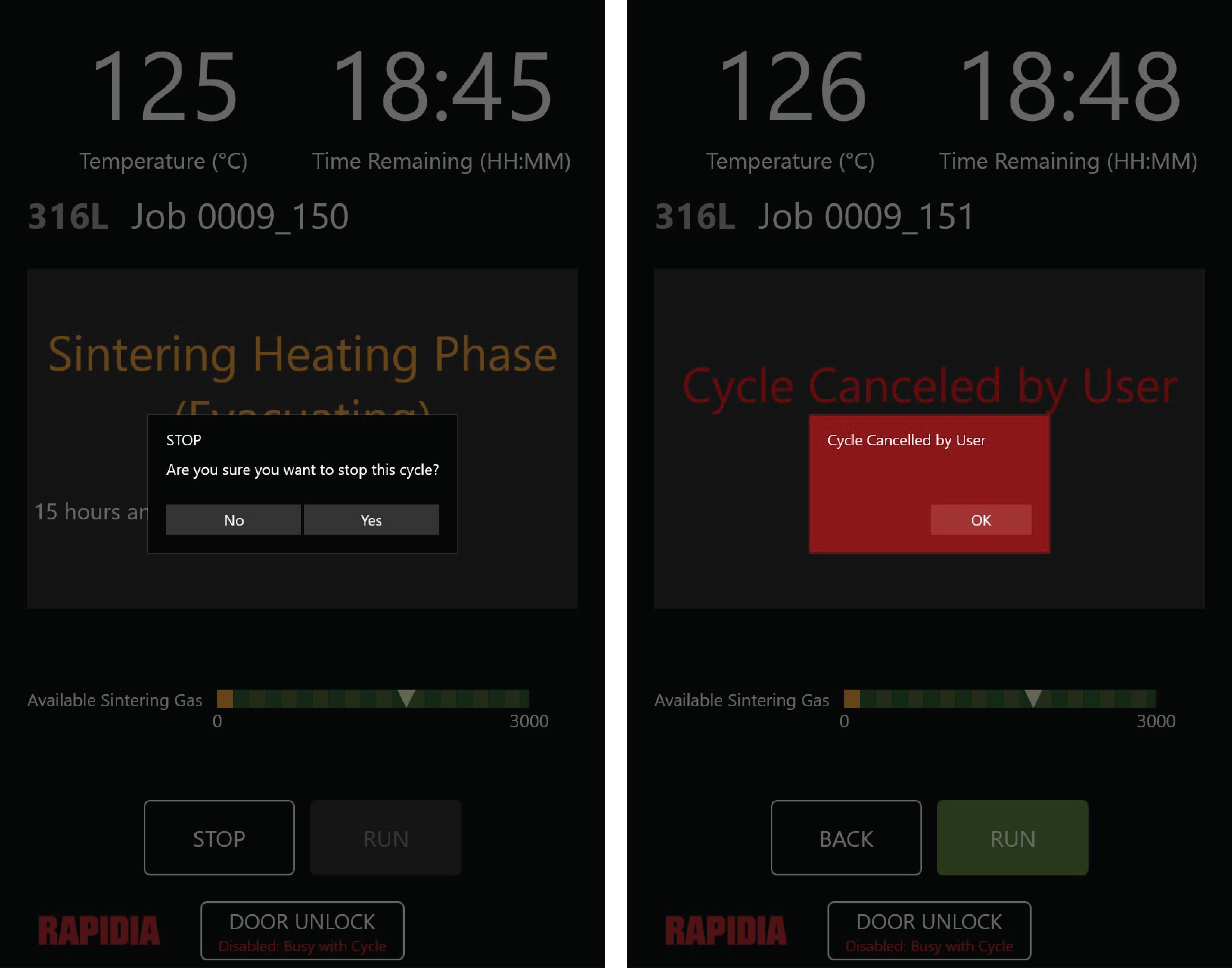
5. To interrupt or stop a run, click the STOP button. A pop-up window will appear; select Yes if you want to confirm aborting the cycle. See here.
6. During the cycle, the furnace will proceed through a “Sintering Heating Phase” that takes the majority of the time followed by a “Sintering Cooling Phase”. See here.
7. Once the cycle is complete, the furnace needs to cool down to a safe temperature. When the furnace is above 150 °C/ 300 F, the door lock disengage function is disabled. After the furnace has cooled below this temperature, the button becomes active.
8. To open the furnace for removing sintered parts:
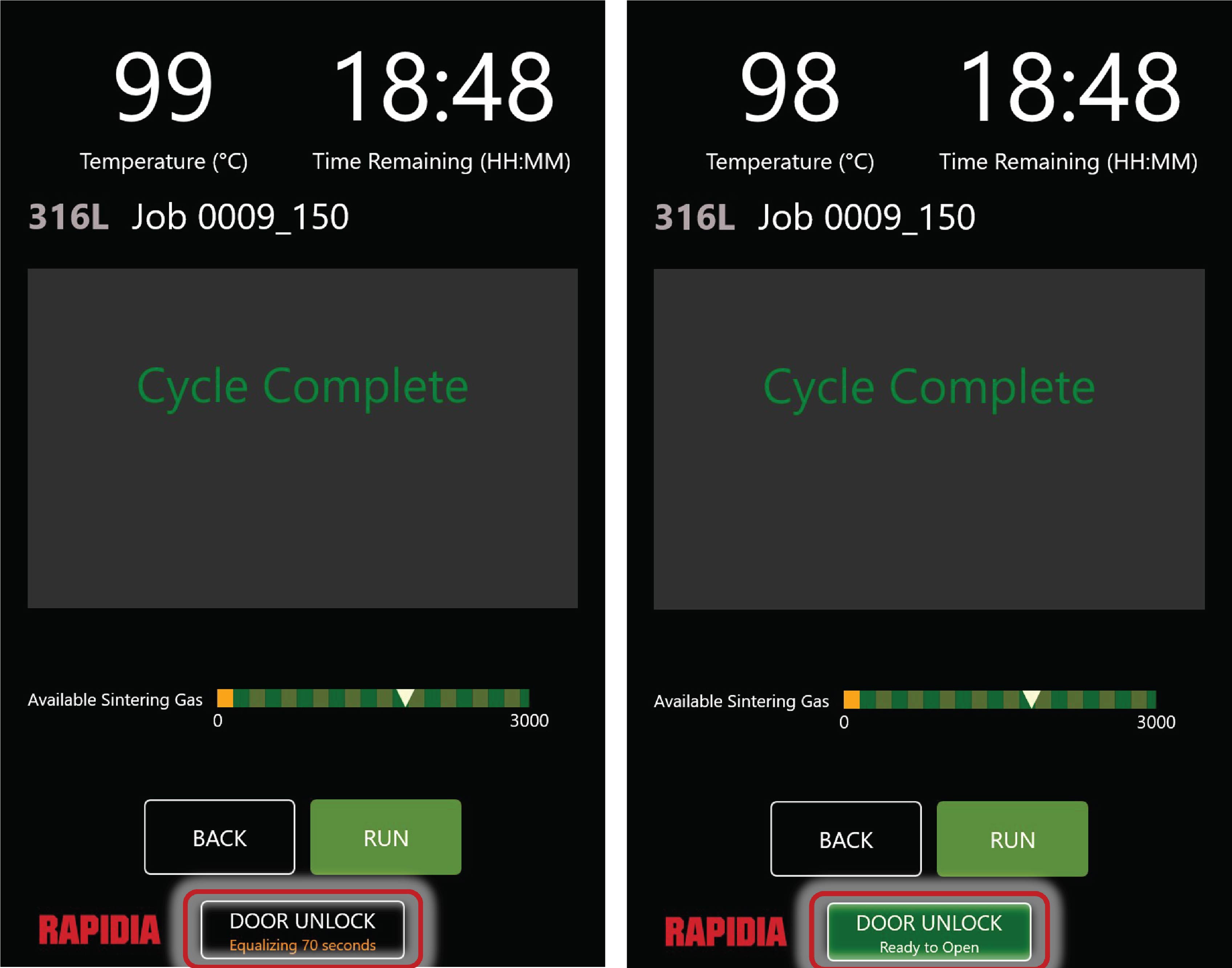
- Click the Door Unlock button. This activates the bleed valve to slowly vent the furnace. Note that the system is still at a reduced pressure of several Torr and needs to reach atmospheric pressure (760 Torr) before the door can be opened. This takes around 100 seconds. After the pressure has been equalized, the Door Unlock button will turn green and the door interlock will deactivate. See (b).
- Open the retort door as described in Retort Overview. If it is not possible to rotate the handle to open the furnace, try rotating the handle clockwise slightly (i.e., in the “Lock Direction”). Press the Door Unlock button, and then try again to open the door by rotating the handle counterclockwise.
- Proceed to Unloading Sintered Parts from The Furnace.
¶ Unloading Sintered Parts from The Furnace
 |
Burn hazard: Parts coming out of the furnace and components of the retort assembly can be very hot. Wear forearm length heat resistant gloves to prevent burns. |
Once the sintering cycle is complete, follow these steps to unload the furnace:
1. Prepare to remove the parts by putting on heat-insulating gloves. Parts are available to remove after 150°C (approximately 300°F). Due to the nature of the point temperature measurement, the temperature of parts may be substantially higher than the temperature displayed on the screen. Proceed carefully and behave as if you are reaching into a hot kitchen oven.
2. Slide the shelves toward the front of the furnace slowly, pulling on the bottom graphite shelf.
3. Remove the shelves, starting with the top shelf. Pick up the shelf by the graphite tray, and place onto a heat-resistant surface (brick or stainless steel recommended).
4. Allow parts to cool sufficiently before touching without gloves. Failure to do so will result in burns.
5. After removing the parts, close the furnace door to prevent contamination of the furnace if there is an extended break between sintering runs.