“Slicers” are programs that decompose part models into a series of line segments that can be traced out by an extruder to reconstruct the model. Rapidia's Conflux 1 Printer is designed to be used with a modified version of the open source slicer Cura.1 Rapidia's modifications to stock Cura make it easy to change material type, nozzle size, and highlight some of the more important options to consider when slicing a part for the Conflux 1 Metal 3D Printing System.
1 While other slicers will be able to generate the necessary files to run on the Conflux 1 Printer, they have not been extensively tested. Speak to a Rapidia Applications Engineer before running the printer using G-code generated by a different slicer.
¶ Slicing for Metal Paste Deposition
The following guide is intended for users that are already somewhat familiar with slicers, and is written to highlight some of the unique considerations that must be taken into account when slicing parts for printing on extrusion based bound metal printers. A variety of good introductions to slicing software and settings optimization exist online. For a good introduction to stock Cura for example, see this webpage.
¶ Getting Started
¶ Installation
If you need to download the latest installation executable, it can be found on our github release page under the Assets tab. The install wizard will guide you through the installation steps.
Once Rapidia Cura is installed, you can set up the printer by adding a non-networked printer as shown here:
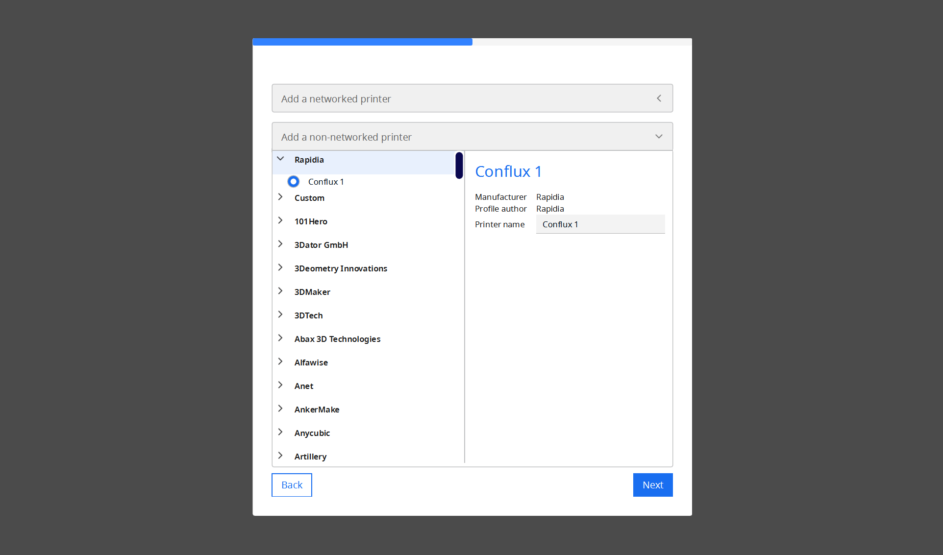
Rapidia Printer Setup, visible the first time Rapidia Cura is opened after installing
¶ Cura Setup
A few settings should be adjusted in Cura after installation to allow for the best use of the slicer.
When first opened, the slicer will have the same material loaded in both Extruder 1 and Extruder 2. Before slicing a part you will need to tell the slicer which material is in each extruder. When printing with support and slicing using Rapidia Cura, extruder 2 should always be set up with support material and extruder 1 should be set up with metal.
Use the bar above the main window to configure Cura for the printer’s physical setup including nozzle diameter and material type.
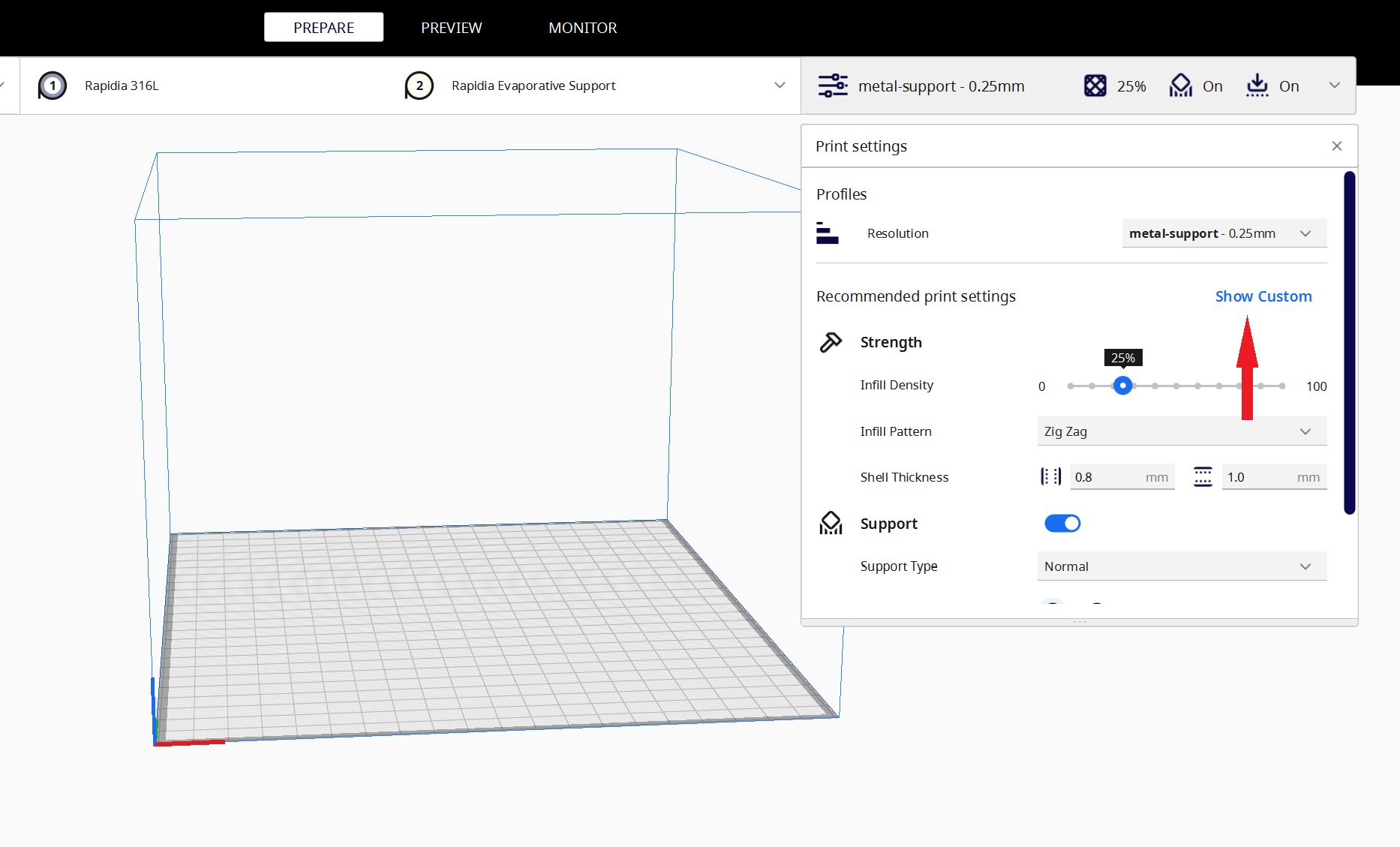
Next, select Custom in the Print settings dropdown to reveal the set of settings often changed when slicing parts for the Rapidia Printer:
¶ Converting 3D Model to STL
Rapidia Cura requires 3D models to be input in STL format (Standard Tessillation Language). The main consideration when exporting a 3D model from CAD software is the resolution of the STL. STL file formats are composed of a dot matrix, connected by straight lines. Thus, curves are approximated by a series of short line segments. Resolution is often expressed as tolerance. The tolerance would be the maximum distance that line segments are allowed to deviate from the true geometry. Since the accuracy of 3D printing is fundamentally limited to about ±0.1mm, there is nothing to gain from exporting at a drastically higher tolerance than this.
Recommended STL tolerance: ~0.025-0.050mm (~0.001-0.002")
To minimize tessalation effect on curved surfaces, decrease the angle tolerance to <1°
STLs exported at much higher resolution will slow down slicing and printing detrimentally. Use our recommended STL tolerance for a good balance of fidelity and usability. See Figure 1.2 for an example of an STL saved at 0.025mm tolerance:
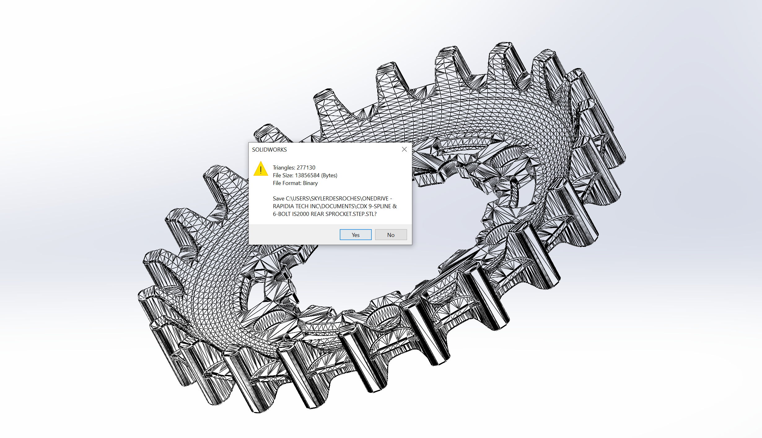
Figure 1.2 - A belt pulley STL, saved at 0.025mm tolerance - file size is acceptable at 13.8MB
.png)
Figure 1.3 - Comparing the surface texture of an STL exported with angle tolerance of 0.5° (left) to 10° (right).
¶ Basic Slicing
¶ Part Orientation
Rapidia Cura uses all of the same features to position and prepare models for slicing as stock Ultimaker Cura. On the left side of the main window there is a set of controls used to orient the model with respect to the print bed. After being selected, parts can be translated, rotated, scaled and flipped.
Considerations
- Stability: the most stable print orientation is usually so that the largest plane is toward the build plate. Very high aspect ratio parts are in danger of breaking or falling during printing or sintering.
- Minimizing support: for the fastest, most economical printing, it is desirable to minimize the need for support. Orient your part so that it minimized the area requiring support (overhangs >45°) and the height of support.
- Resolution: Print accuracy is high in the X- and Y-axes, while the layer height (standard is 0.25mm) creates a limit on Z-axis resolution. Orient the part so that critical dimensions are in the horizontal plane.
- Surface finish: for Metal Paste Deposition, walls usually have a smoother surface finish than tops or bottoms. When surface finish is critical, orient the part so that the critical area prints as a wall.
The following options are captured by the default settings found under the Profiles drop-down menu in the print settings window. If this view of the profiles is not visible, click on the Custom button at the bottom of the print settings page.
¶ Part Infill Density
- Solid:
Set 'Infill Density' to 100%. This option will slice the part such that its cross section will be solid. Use when the part needs to access the full strength of the metal. - Sparse:
Set ‘Infill Density’ to 20-99%. This option will slice the part so that the part is composed of an outer shell and an internal lattice. Use this option to reduce the material used, the mass of the part, and the time required to print it. Below 20%, the infill will not adequately support the top.
¶ Infill Pattern
Line pattern for the infill. The default profile uses zigzag infill patern, to offer great strength in the horizontal plane and fast printing. Gyroid infill also works well for Metal Paste Deposition, and offers more isotropic mechanical properties.
When printing at 100% infill density, use only zigzag or concentric infill patterns. Other patterns, such as gyroid, will prevent the print from achieving voidless 100% fill.
¶ Layer height
Thickness of slices in the z-direction. Large slices will give the part a coarser texture and resolve vertical features less well, but small layer heights will take longer to print and can be difficult to calibrate.
Default layer height when printing with a standard 0.4mm nozzle is 0.25mm for the best balance of resolution and printability.
Layer heights below 0.2mm are not recommended for printing with a 0.4mm nozzle.
¶ Wall line count
Number of walls in the exterior shell of the part. Our experience has shown that three is a good default, but use one when printing parts that need to minimize porosity.
Wall thickness is a function of wall line count and line width.
final wall thickness = wall line count × line width / scale factor
¶ Slicing Profile Selection
- No Support:
This option will print the part directly on the bed without any support for overhangs and without any sintering raft. This option is ideal for simple parts that can be designed to optimize for the printing and sintering process. - Evaporative Support:
This option will print the part on a sintering raft and support any overhangs with support material that burns away during sintering. - Metal support:
This option will print the part on a sintering raft and support any overhangs with more metal. Metal supports provide support through sintering, to help prevent sagging during sintering. The metal supports will be separated from the parts using evaporative support material which will inhibit sintering between the two structures and prevent them from bonding.
¶ Support Structures
Like other extrusion-based printers, the Rapidia system is constrained by the need for geometry from one layer to be supported by material from previous layers to resist the sagging or drooping that would otherwise result due to the force of gravity on the filament. Additionally, because the part must also undergo sintering to achieve full strength, extra considerations must be taken into account to adequately support a part and prevent distortion. The Rapidia printer addresses both issues with a single, dual-purpose support material.
The support material is predominantly composed of a polymer designed to burn away during sintering, but also contains a sintering inhibitor which prevents any two layers of metal separated with support from bonding to one another during sintering. By default, the Rapidia printer is set up with two extruders: one that prints metal feedstock, and another that prints the support material. This allows two types of support to be used: Evaporative support structures, and Metal support structures with an interface layer.
Slicing profile default: overhangs steeper than 40° generate support
Maximum unsupported overhang: it is possible to print overhangs up to ~47° without support, depending on area of overhang
- Evaporative Support Structures for support in printing
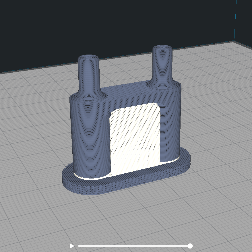
The above part requires support material to be able to print the bridge but does not need to be supported during sintering.
Evaporative support structures serve the same function as soluble support does in filament based plastic 3D printing: they provide a temporary, easily removable platform on which subsequent layers of the model material can be printed. In the case of the Rapidia system, instead of using a solvent to remove them, columns of the material are simply burned away during sintering.
Evaporative support structures can be used to support shallow and stiff features that exceed the recommended overhang angle (but do not require support in sintering), and in areas where metal support will be difficult to remove, such as in a vessel with a small opening. Because the sintering inhibitor, which makes up a small fraction of the support material, will not decompose in the furnace. A white powdery residue from this inhibitor will remain in areas that were previously occupied with the evaporative support. In the case of the vessel, for instance, this small amount of sintering inhibitor will need to be flushed from the cavity after sintering if the designer anticipates that it will interfere with the end use of the part.
- Metal Support Structures for support in printing and sintering
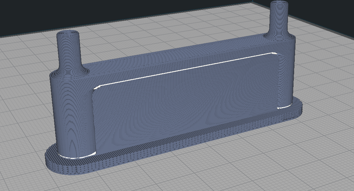
Metal support generated by Rapidia Cura when the “Metal Support” option is selected.
A part that features a long span that will need to be supported during sintering to avoid drooping. Metal supports are automatically generated with a 0.5mm layer of evaporative support material between the support structure and the part, which acts as a separation layer and allows removal of support structures after sintering without any cutting.
¶ Considerations for Slicing Parts with Support
Using support material has a few drawbacks:
- Increased printing time
- Increased volume of material used
- Rougher surface finish at support interface
- Increased time to set up and calibrate machine before printing
¶ Advanced Slicing
¶ Bed temperature
Using a high bed temperature will ensure that the part is completely dry by the time it’s done printing. However, it will also tend to cause large parts to curl and peel off the bed. When printing with a lower bed temperature, remove the part from the printer by gently sliding the build plate off of the bed with the part still adhered. Set the build plate somewhere warm to dry. Parts with section thicknesses over 25mm may benefit from drying in a conventional oven at ~90°C.
¶ Modifier volumes
It is possible to selectively set different parameters in different areas of the print using modifier cubes (or other shapes). To place a modifier cube, select the part to modify, then select the "Place Modifier Cube" tool as shown below, then click on your part where you'd like to place the cube. Once placed, it is simple to move the modifier cube, so don't worry about getting exactly right the with the first click.
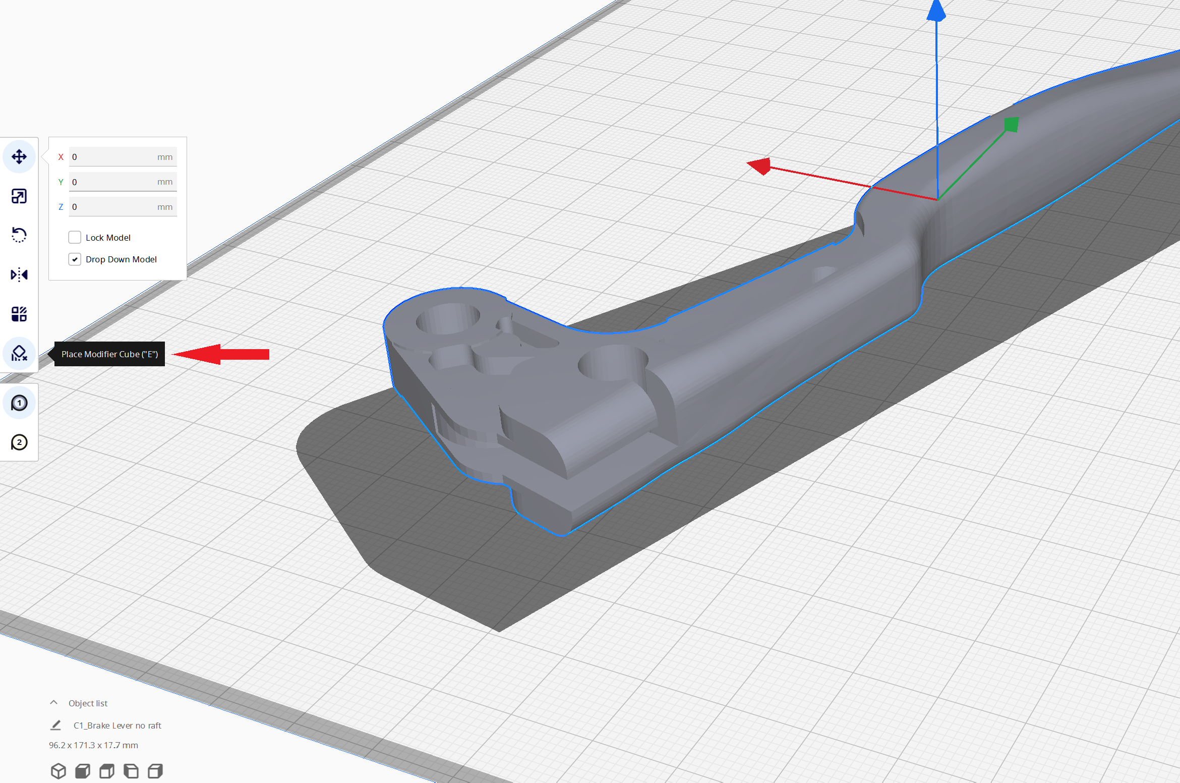
With the modifier cube selected, use the tools on the left hand tool bar to change its dimensions and locations. When the modifier cube is selected, the "Per Model Settings" utility (directly above the Place Modifer Cube tool) gives four options for what do in the specified volume:
- Normal Model will treat the modifier volume with the same slicing parameters as your part.
- Print as Support will treat the modifier volume with the same slicing parameters as support structures.
- Modify Print Settings allows you to select any slicing parameters to modify in that area. For example, if you want 25% infill density throughout most of your part, but 100% infill density around a feature where you plan to post-machine, use this tool, select Infill Density as your parameter to modify, and then set the desired infill to be applied only with areas of overlap between your part model and the modifier volume.
- Modify Support Settings is similar to Modify Print Settings, but only modifies areas where support rules apply. The most common use of this tool is change areas of evaporative support to metal support or vice versa. It will also allow you to delete support structures in the areas of overlap, but unchecking the "Generate Support" option.
For more details, see this video:
How To: Placing Support Modifier Cubes from Rapidia on YouTube.