Different nozzle tips offer differing printing results, our default nozzle diameter is 0.4mm which has a fine balance between deposition speed and minimum feature size. Some users may opt to use a larger 0.6mm nozzle diameter to trade off some of the minimum feature size to increase the paste deposition speed. This article describes the necessary steps to physically swap between the two nozzle sizes and what software related changes need to be made to the slicer to accommodate the different nozzle sizes.
¶ Part Comparison of the Nozzle Sizes:
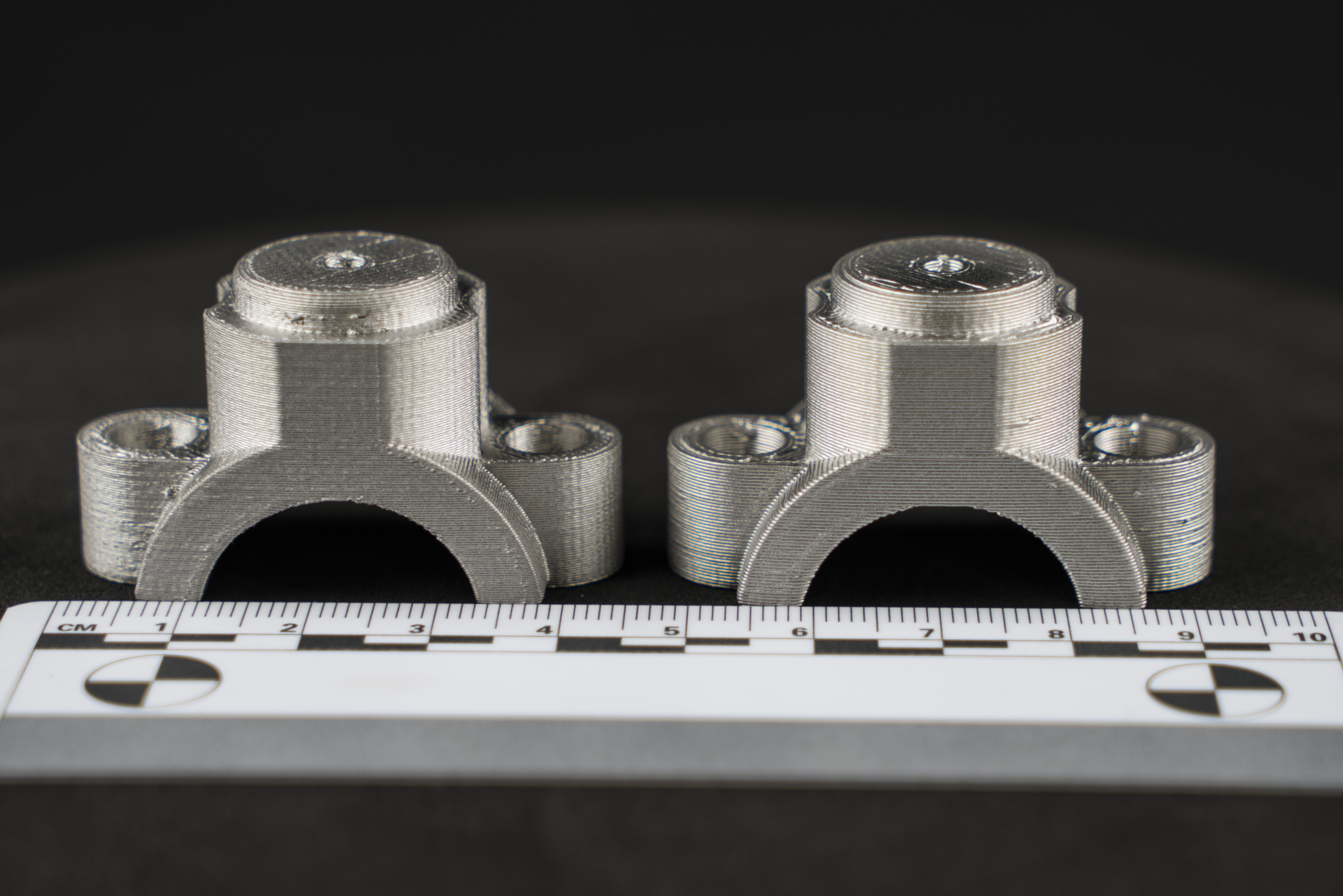
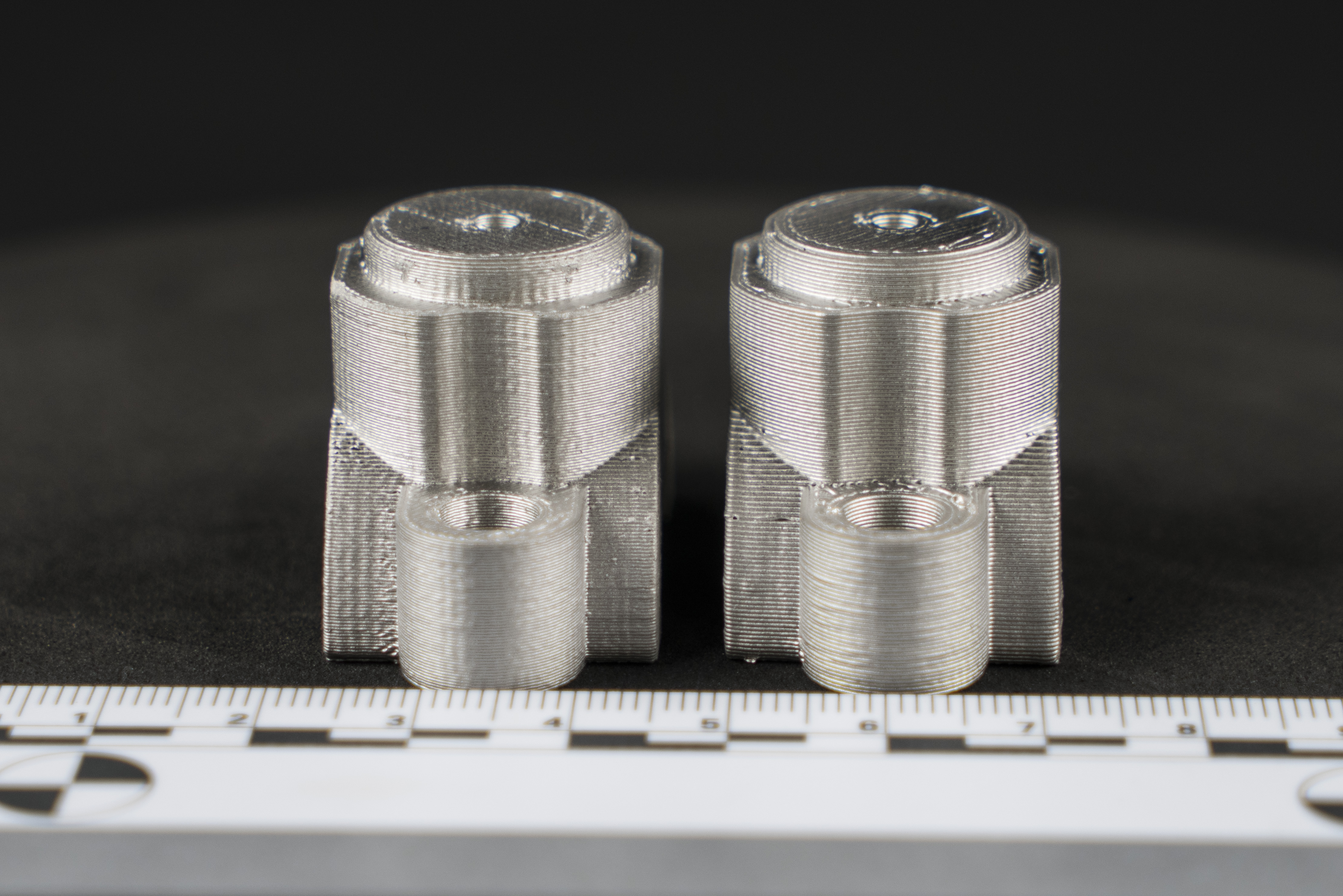
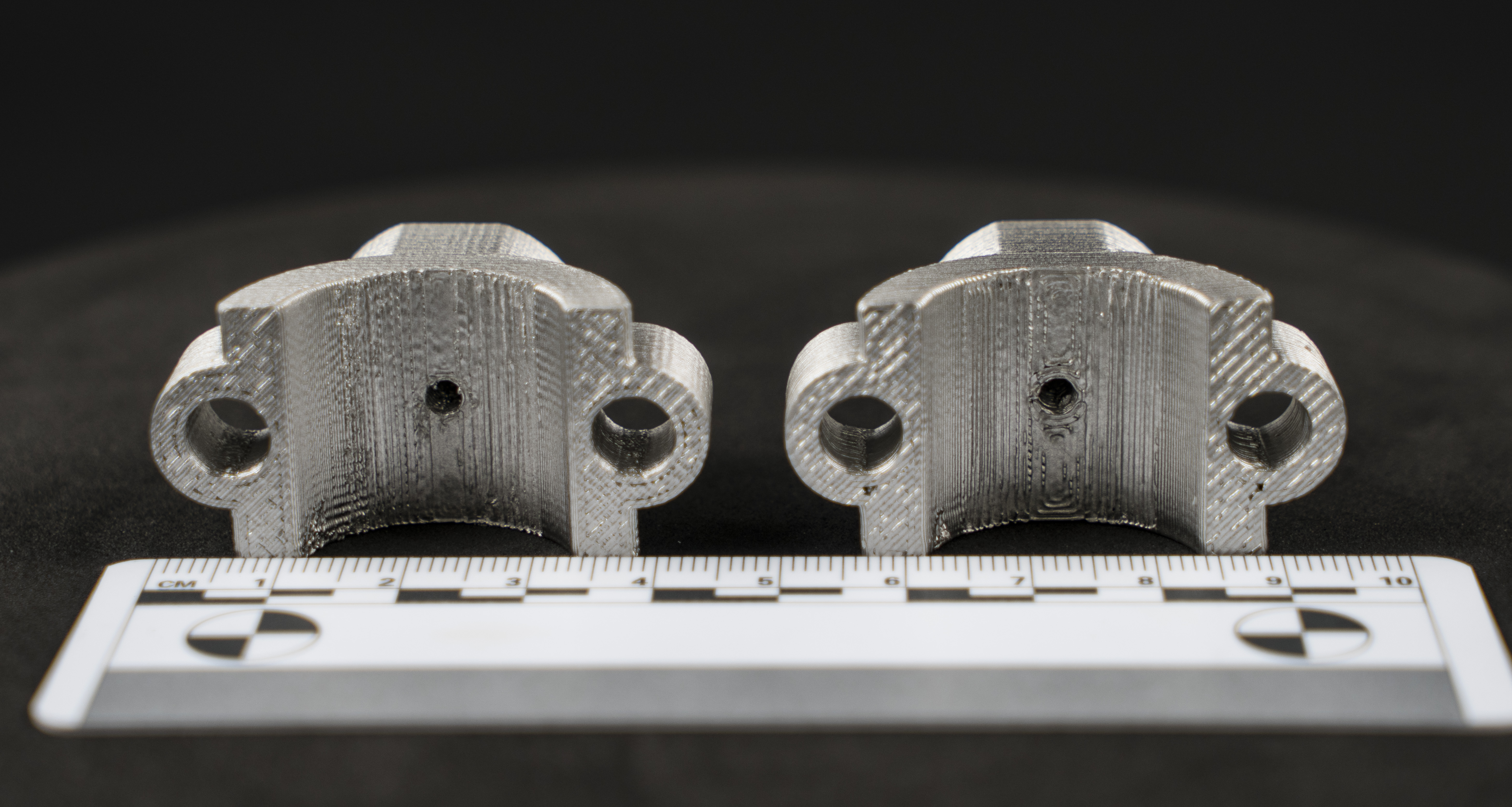
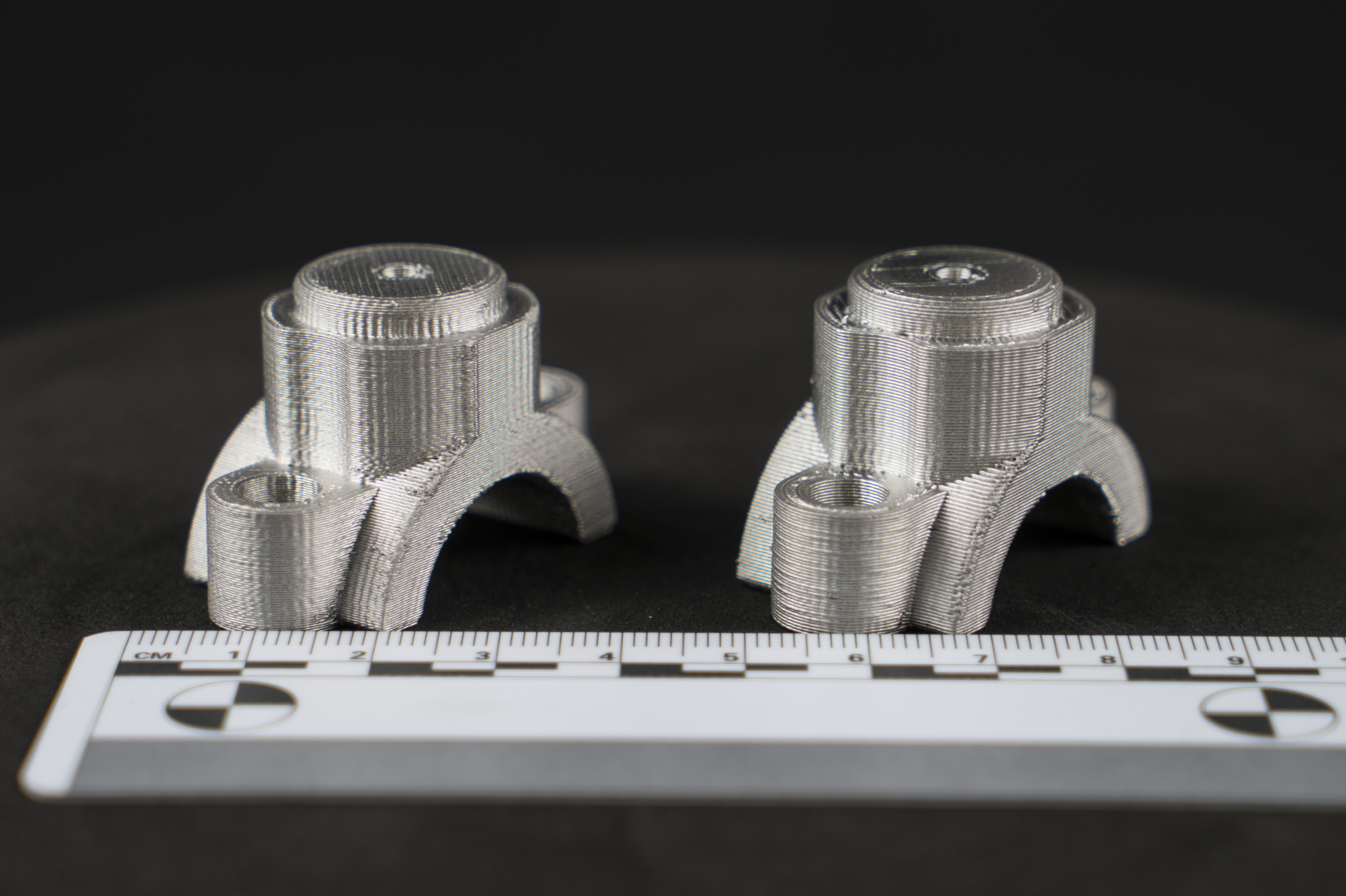
The same part geometry was printed with a 0.4mm nozzle (left) and a 0.6mm nozzle (right) to illustrate the surface and detail trade-offs between the two tip sizes.
The 0.4mm samples shows noticeable finger, tighter layer lines and crisper resolution on small features - the holes, fillets, and chamfers all hold their geometry more cleanly. By contrast the 0.6mm sample lays down a visibly wider bead, resulting in coarser, more pronounced ridging on vertical walls and softer, less defined edges around small features. This is especially clear on the bottom surface where the metal supports were removed; the 0.6mm print shows a rougher finish compared to the smoother underside of the 0.4mm part.
This difference in resolution comes with a meaningful time trade-off: the 0.4mm nozzle took 2 hours 30 minutes to print the part, versus the 1 hour 30 minutes for the 0.6mm nozzle - a 40% reduction in print time. For parts where fine details and surface finish are less critical, the 0.6mm nozzle offers a substantial throughput advantage.
 |
 |
|
|
¶ Physical Nozzle Replacement:
| Required Tools for this Procedure |
|---|
| Adjustable Wrench |
| Nozzle Tip Removal Tool |
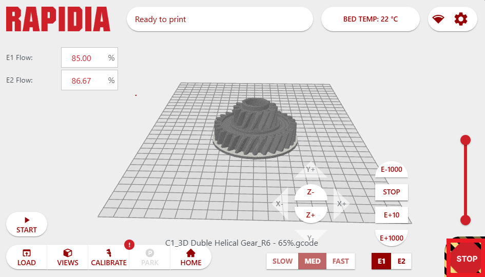
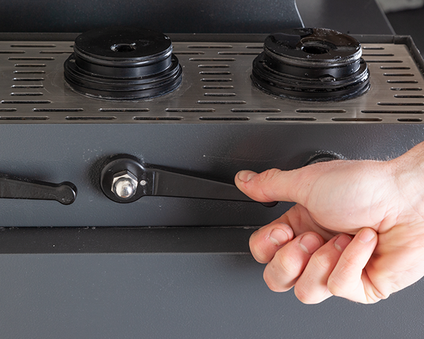
- In the host software hit the E-Stop button so that all the motors on the printer are de-energized. Also ensure that all paste pressurization handles are in the lowered position so that the system is not pressurized.
 |
 |
2. Using an adjustable wrench, remove the nozzle from the primary extruder, ensuring to clean it before proceeding to the next step.
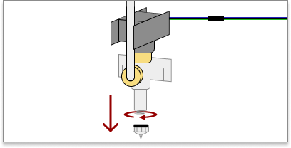
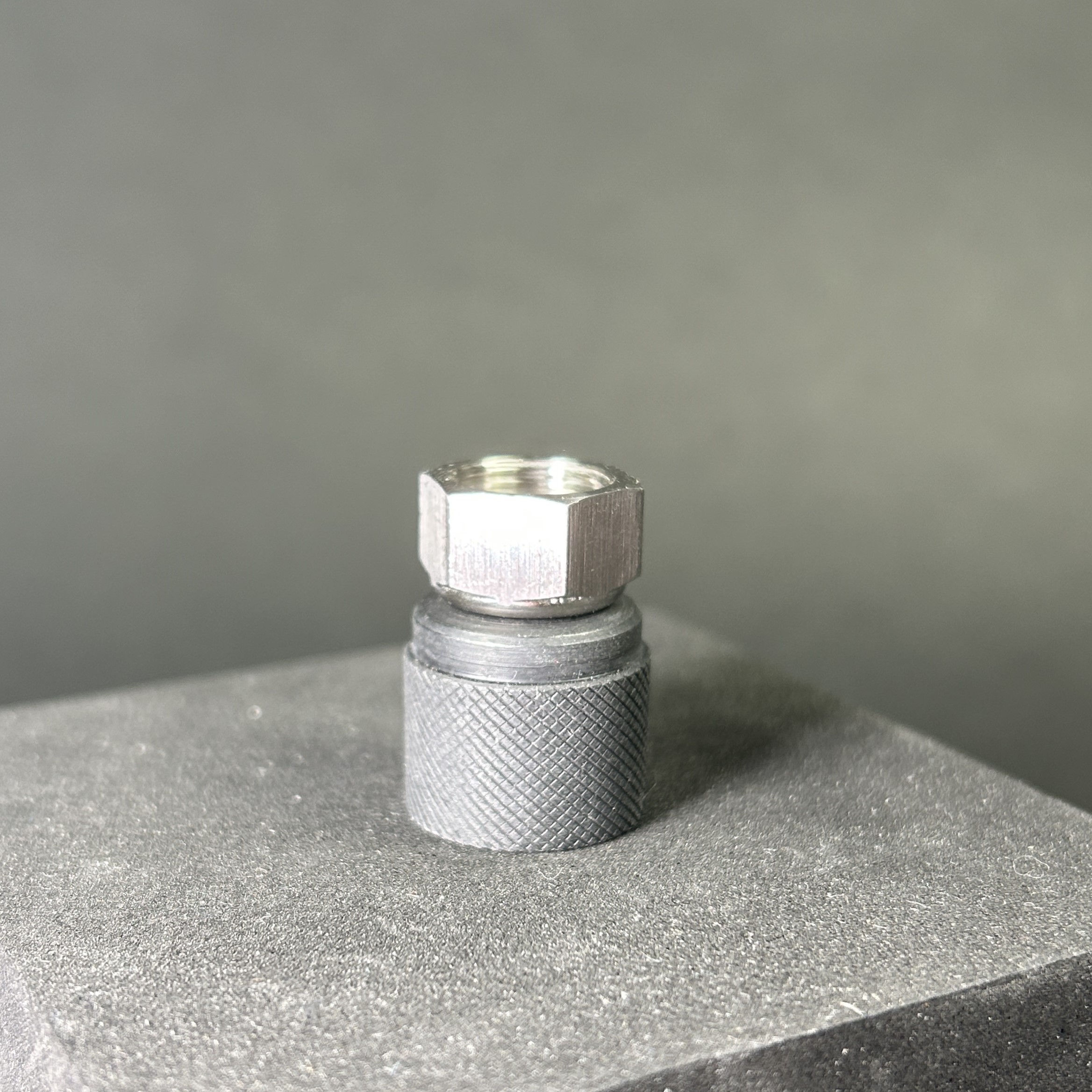
3. Use the nozzle tip removal tool to remove the nozzle tip from the nozzle.
 |
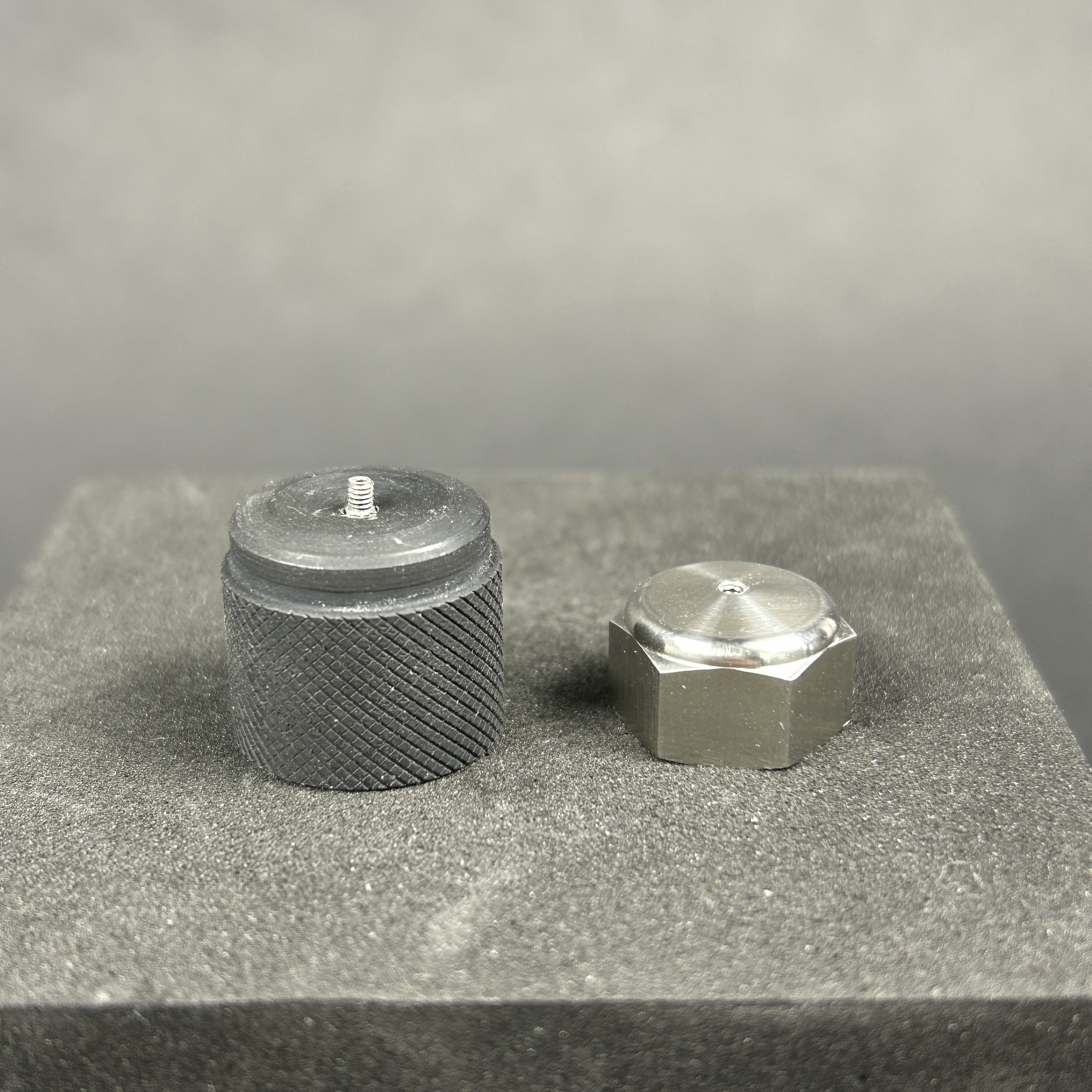 |
4. Install the replacement nozzle tip using the nozzle tip removal tool. Be careful not to cross thread the tip into the nozzle.
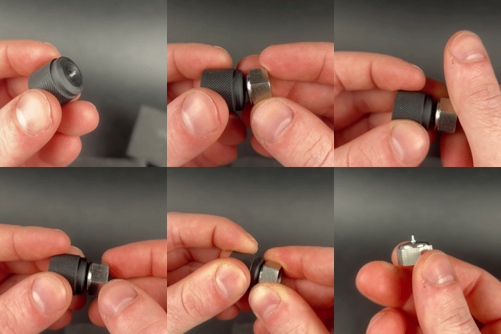
5. Install the nozzle with the replacement tip affixed back onto the extruder. Use an adjustable wrench to ensure things are properly secured.
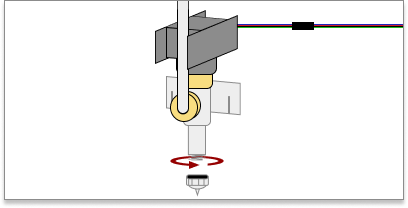
6. Repeat steps 2 - 5 on the secondary extruder & re-pressurize your materials.
¶ Software Related Changes:
Many of the extrusion related settings in the slicing software are related to the nozzle diameter employed on the system; profile files can be imported into Cura which will resolve many of these settings, however there are a few machine settings that will need to be manually updated:
¶ Editing the Machine Settings in Rapidia Cura:
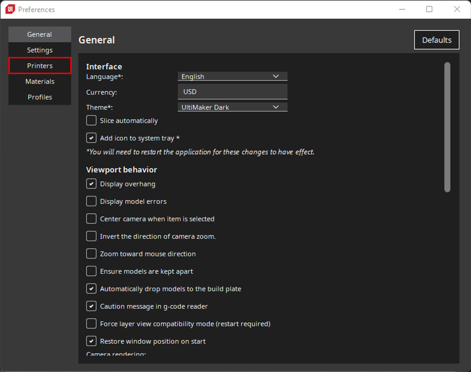
- In Rapidia Cura, go through Preferences -> Configure Cura
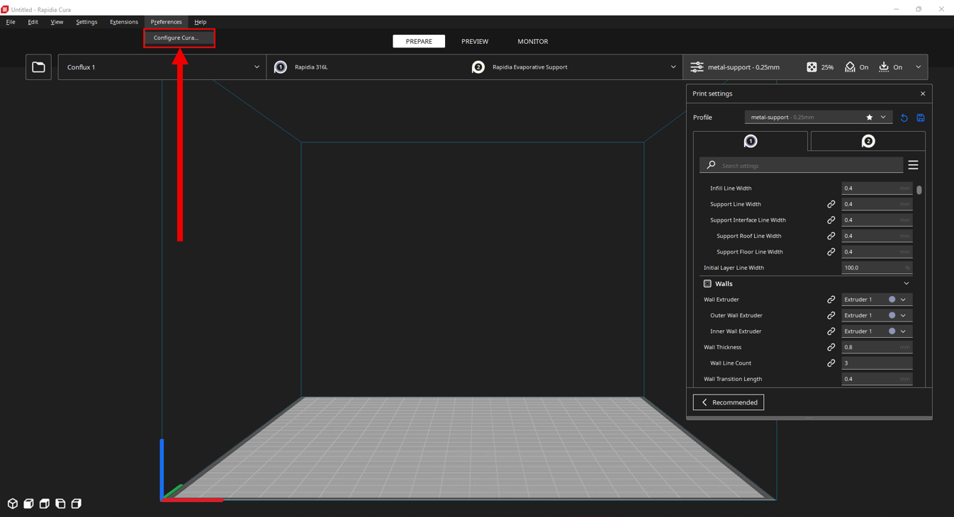
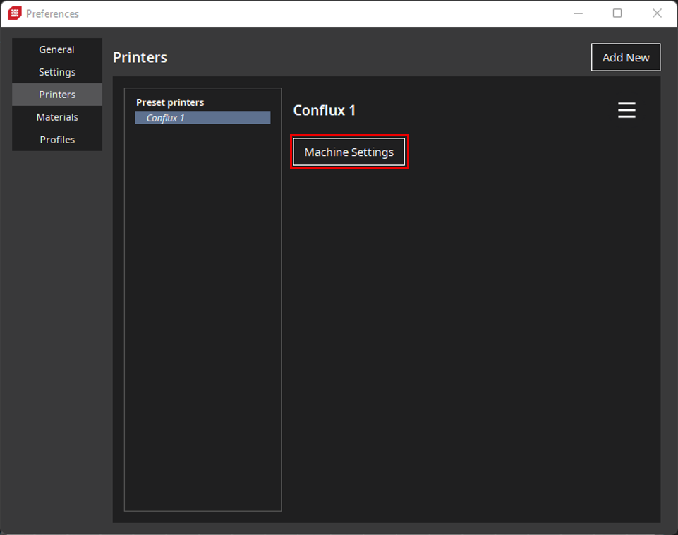
2. Go to the Printer tab in the Preferences Window & select Machine Settings:
 |
 |
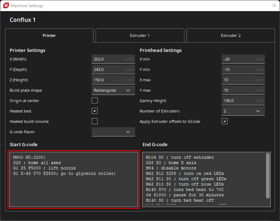
3. On the Printer page of the Machine Settings, edit the first line of the Start G-Code directory depending on the nozzle diameter installed:
| Nozzle Size | Start G-Code first line |
| 0.4mm Nozzle | M900 K0.0200; |
| 0.6mm Nozzle | M900 K0.0215; |
- The numeric value following the K in the first line dictates the pressure advance the printer will use when generating G-Code. The pressure advance controls the internal pressure of the nozzle to ensure smooth consistent flow of paste when the print head change speed. When accelerating it pushes a tiny bit extra paste early to prevent thin spots, when decelerating it reduces the push early to prevent blobs, stringing, and bulging corners. Different nozzle diameters change how easily paste escapes the nozzle, each nozzle size requires its own fine-tuned pressure advance value to keep lines uniform.
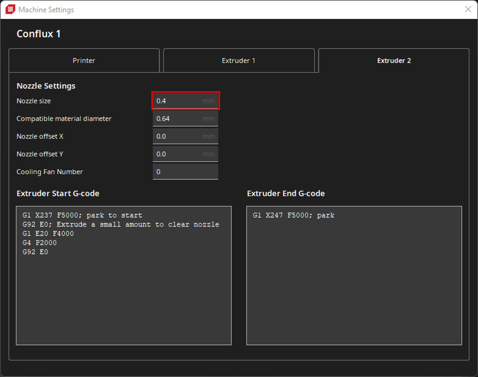
4. Navigate to the Extruder 1 tab of the Machine Settings & update the Nozzle Size field corresponding the to the nozzle size installed on the extruder:
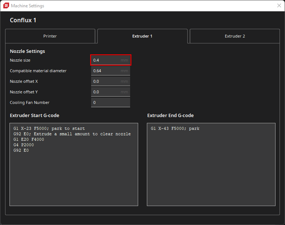
5. Navigate to the Extruder 2 tab of the Machine Settings & update the Nozzle Size field corresponding to the nozzle size installed on the extruder.
¶ Importing Printing Profiles
- Download the corresponding profile depending on the nozzle tip size installed:
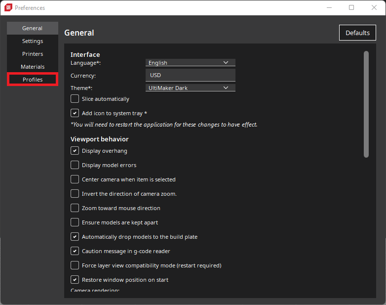
2. In the preferences window navigate to the Profiles tab:
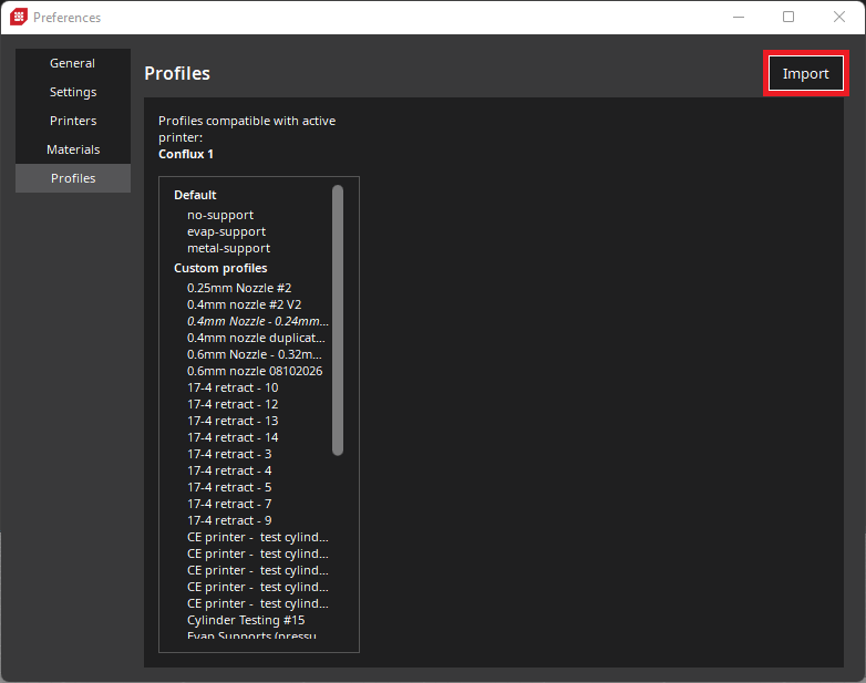
3. Click the Import button and select the profile that was just downloaded:
 |
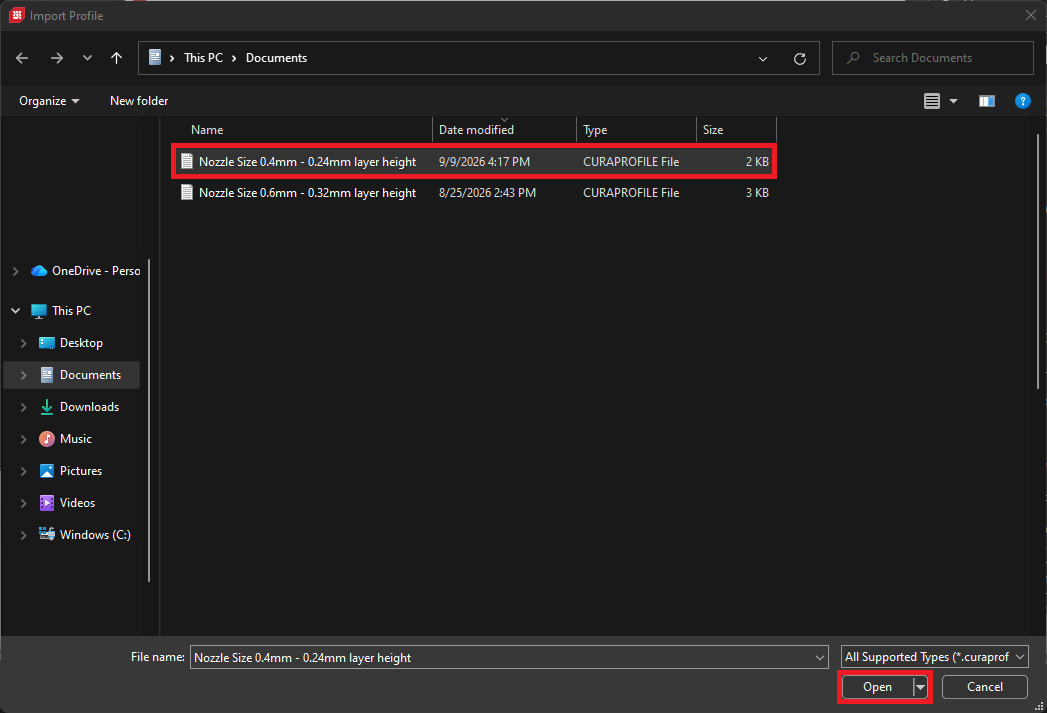 |
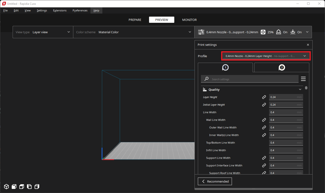
4. Ensure that you have the downloaded profile selected in the print settings before putting it to use.
¶ Retraction Tuning with the Downloaded Profile
There is a small bit of tuning to perform on the profiles downloaded in the previous step to accommodate your specific rotor and stator fitment. By default these profiles have the Retraction Extra Prime Amount set to 0.0 - this value controls how much extra material is pushed through the nozzle right after retraction, which severely influences the z-seam quality.
- Download the following STL file and open it in Rapidia Cura
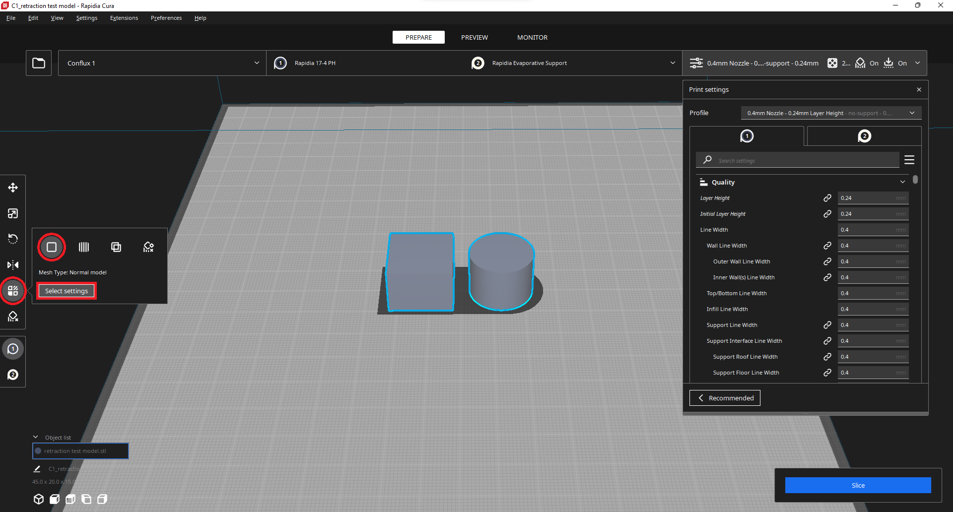
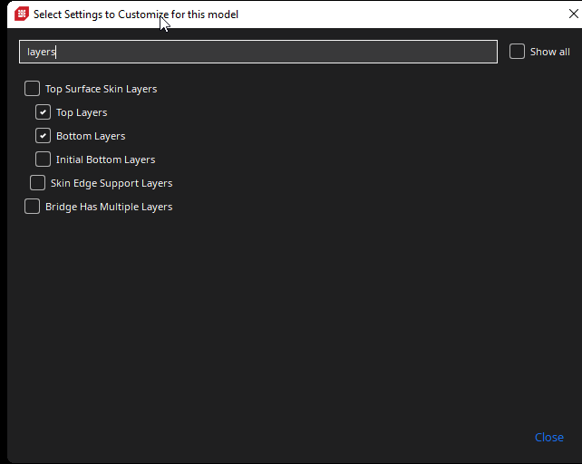
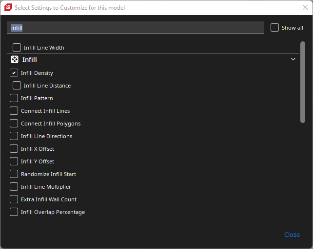
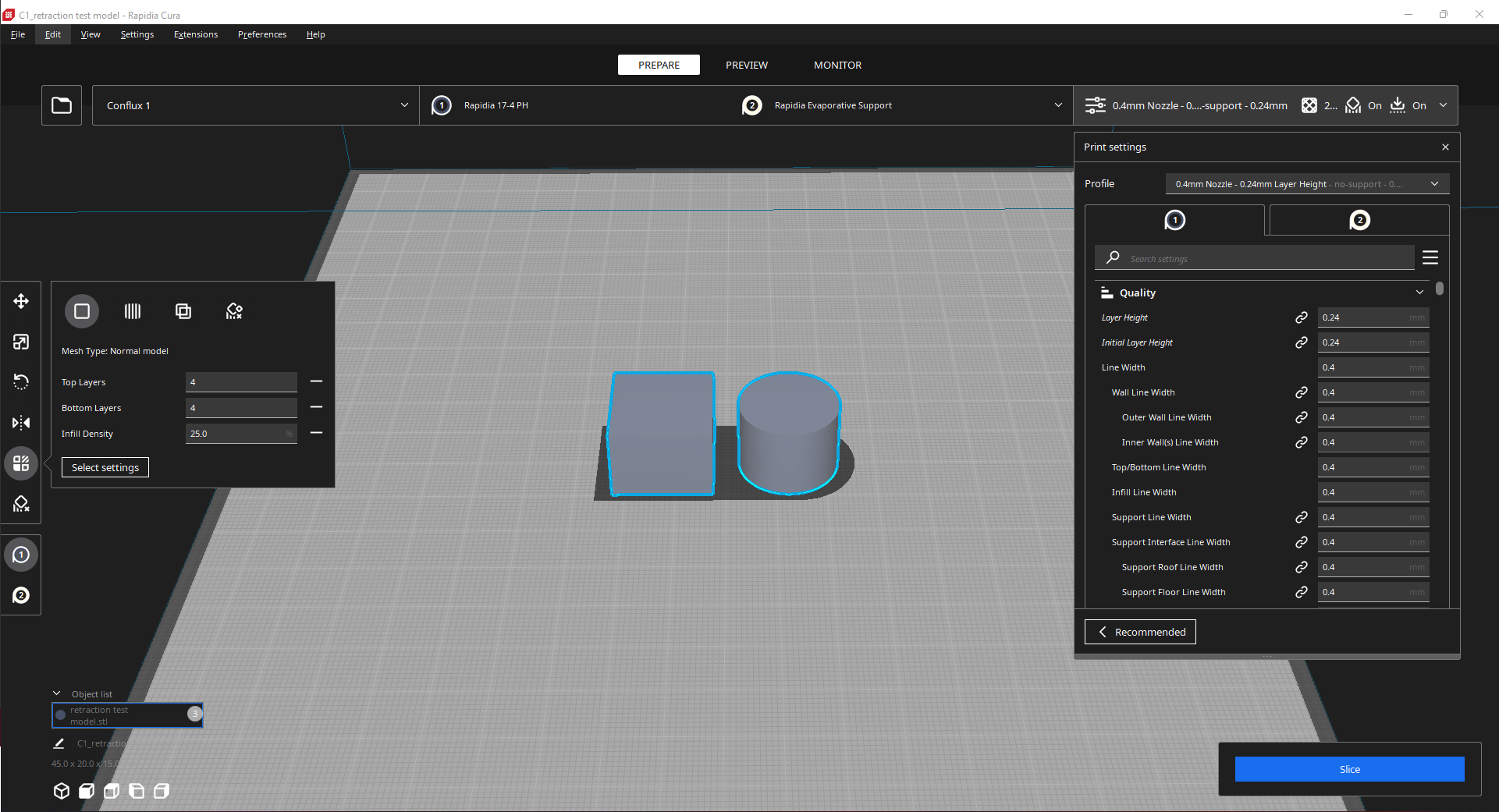
2. In Rapidia Cura select the model and adjust the Per Model Settings so that you have access to Top Layers, Bottom Layers, and Infill Density:
 |
 |
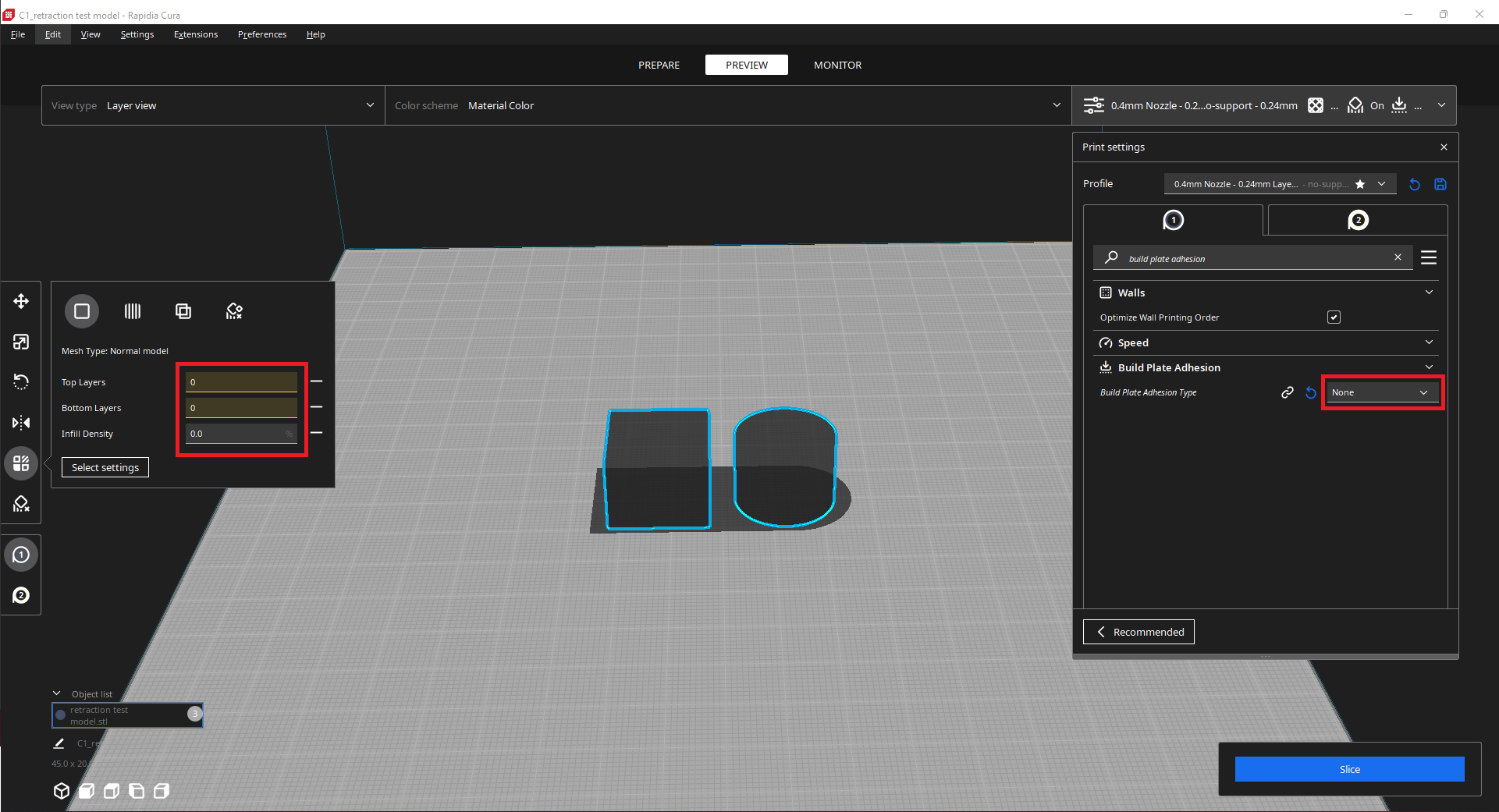
3. Adjust the per model settings selected in the previous step all to 0. Also change the Build Plate Adhesion Type to None:
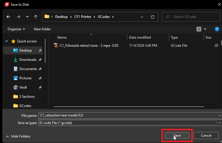
4. Slice the part and save the G-Code ensuring that you note the Retraction Extra Prime Amount in the G-Code name:
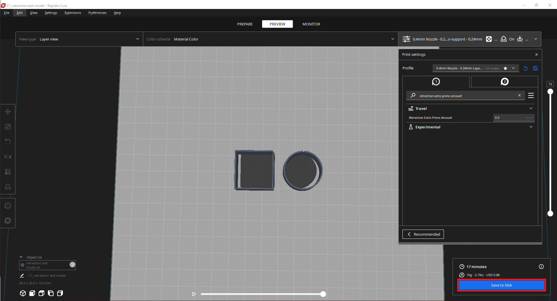
With the per model settings adjusted to 0, the preview of the G-Code should only display the walls of the models; no top layers, bottom layers, infill, or rafts just as seen in the photo above.
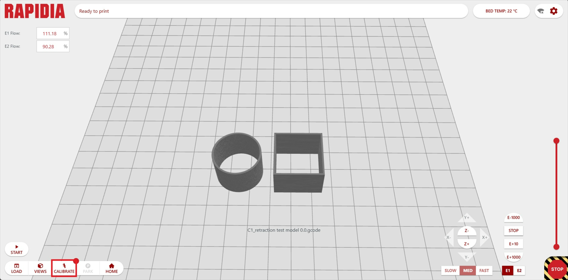
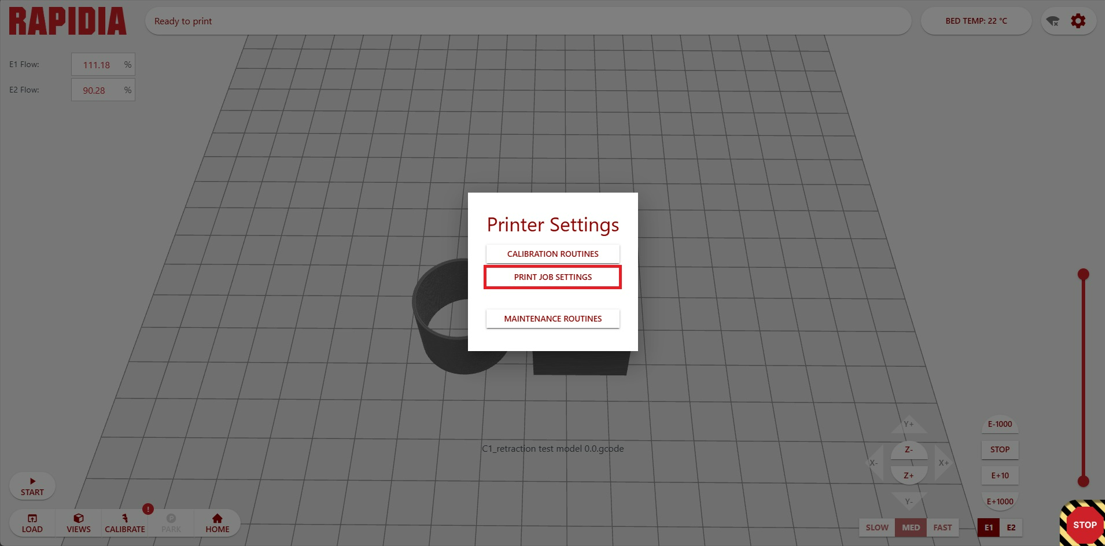
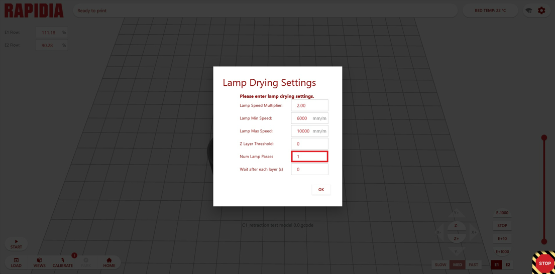
5. Upload the G-Code file that was just generated to the printer host software and adjust the number of lamp passes to 1 in the print job settings:
6. Start the print and proceed to the next steps while waiting for it to complete.
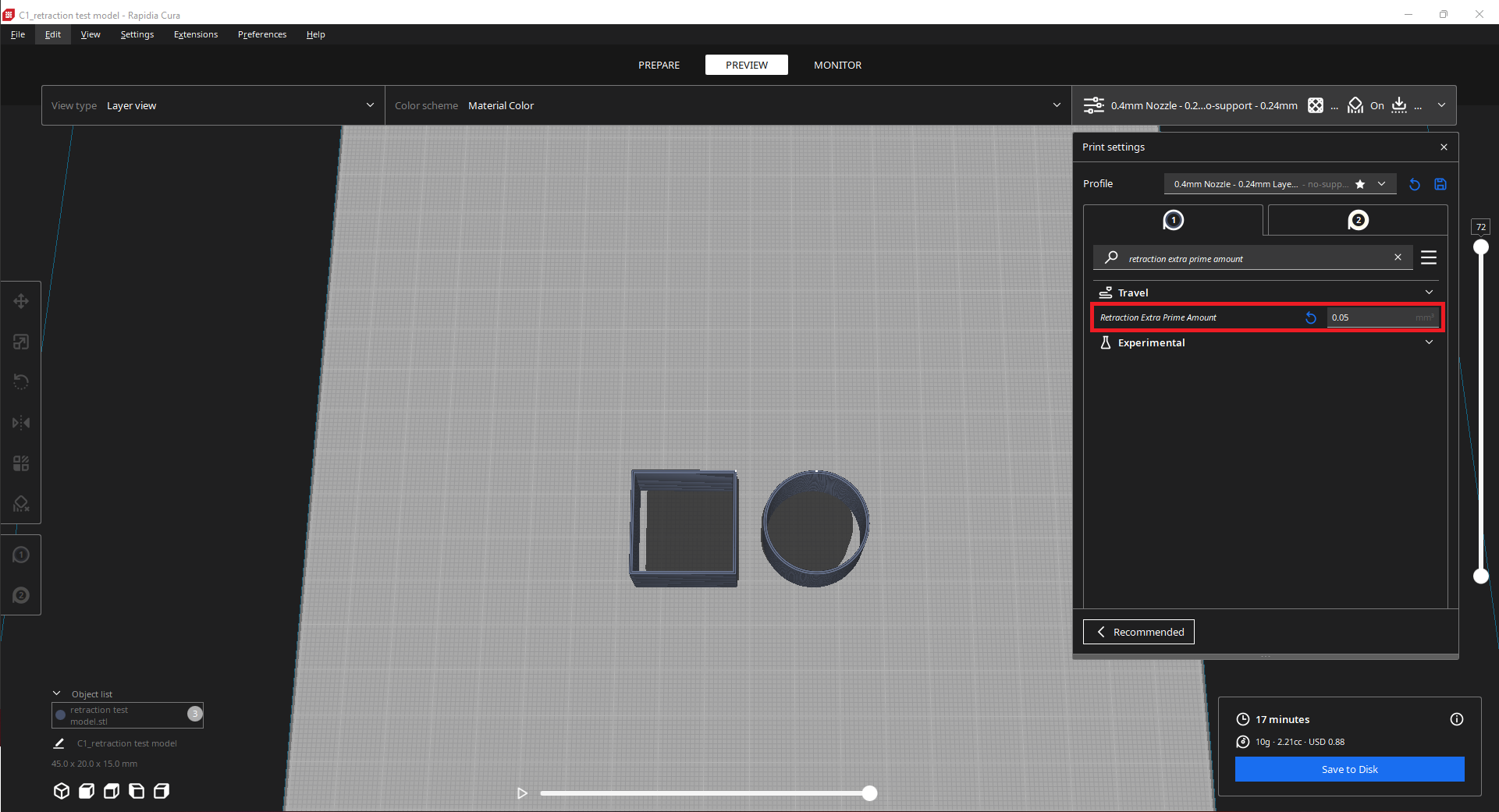
7. Jump back into Rapidia Cura and update the Retraction Extra Prime Amount to 0.05. Ensure that the settings dictated earlier are still present before saving the G-Code:
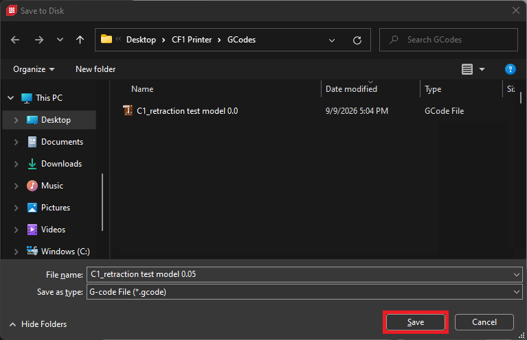
8. Save the G-Code with the updated Retraction Extra Prime Amount in the file name:
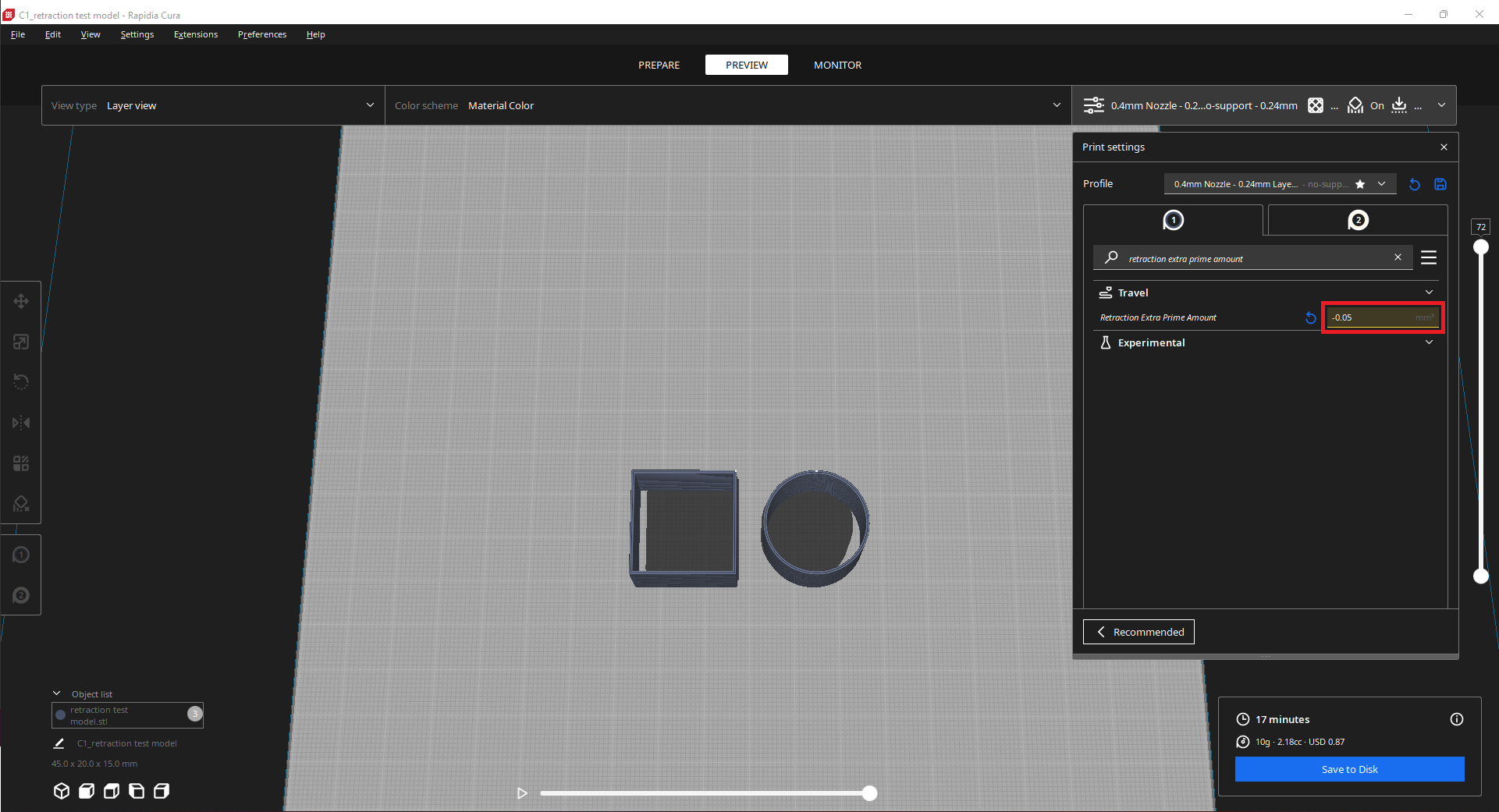
9. Update the Retraction Extra Prime Amount to -0.05:
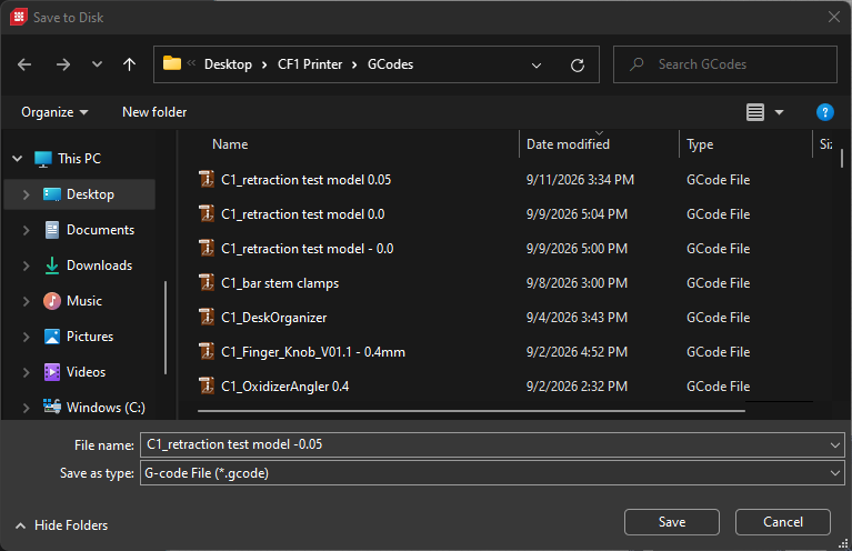
10. Save the G-Code with the Retraction Extra Prime Amount in the file name:
11. Wait for the print started earlier to finish, then remove the parts from the printer and clean the build plate. There is no need to wait for the bake off cycle to complete before removing the parts as the moisture in the parts will be removed by the lamp passes. Once the LED lights inside of the printer turn red hit the ESTOP button in the host software until the LEDs go back to their standby white color.
12. Upload the G-Code file sliced with the Retraction Extra Prime Amount set to 0.05 to the host software; adjust the number of lamp passes to 1 and start the print.
13. Repeat step 11 once the print started in the previous step has stopped depositing material.
14. Upload the G-Code file sliced with the Retraction Extra Prime Amount set to -0.05 to the host software; adjust the number of lamp passes to 1 and then start the print.
15. Wait for the printer to stop depositing material and remove the parts, ensuring the clean the print bed once the parts have been removed.
¶ Determining the Ideal Retraction Extra Prime Amount:
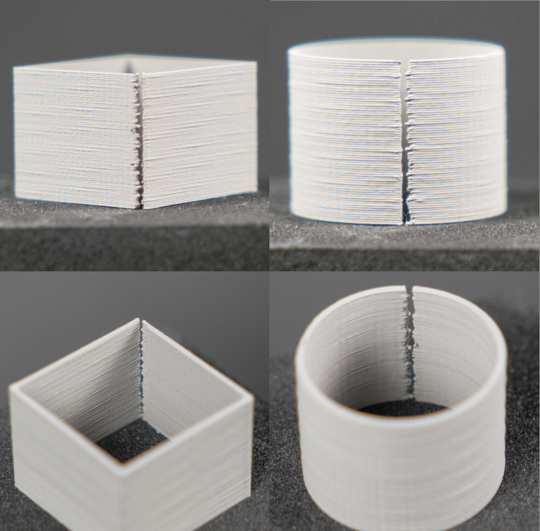
Now that the retraction tuning model has been printed with a range of Retraction Extra Prime Amounts, we can inspect the resulting green parts to determine which value yielded the best quality on the Z-Seam. From here if the quality of the z-seam is not what you desire, you can continue iterating the Retraction Extra Prime Amount until the desired print quality is reached.
| Retraction Extra Prime Amount: -0.05 | Cube | Cylinder |
| Exterior Z-Seam |
|
|
| Interior Z-Seam | ||
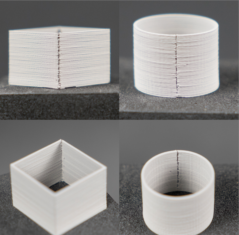
| Retraction Extra Prime Amount: 0.0 | Cube | Cylinder |
| Exterior Z-Seam |
|
|
| Interior Z-Seam | ||
On this next print with Retraction Extra Prime Amount set to 0.0, we can see that the void is still present on the Z-Seam albeit the void is much smaller than the previous print.
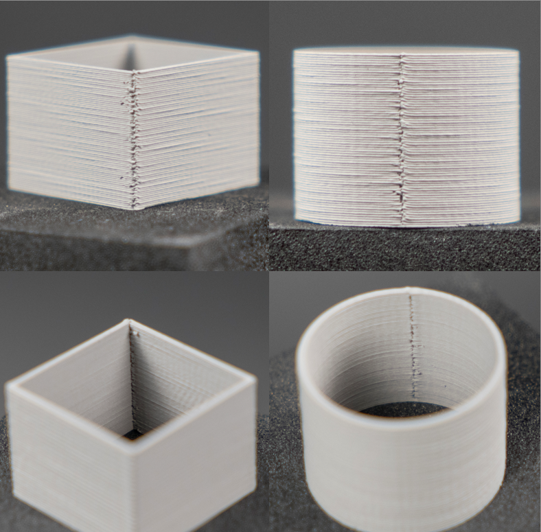
| Retraction Extra Prime Amount: 0.05 | Cube | Cylinder |
| Exterior Z-Seam |
|
|
| Interior Z-Seam | ||
Moving on to the print with Retraction Extra Prime Amount set to 0.05 we start to see the external Z-Seam has started to print with minimal voids, but the internal Z-Seam still is printing discontinuously as seen by the shadow on the interior of the cube.
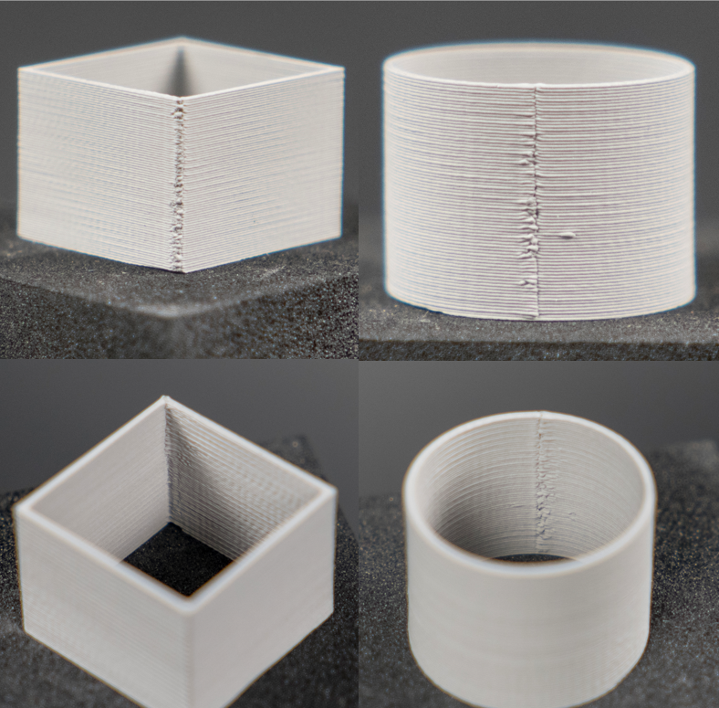
| Retraction Extra Prime Amount: 0.08 | Cube | Cylinder |
| Exterior Z-Seam |
 |
|
| Interior Z-Seam | ||
As I did not receive the best quality throughout my rounds of testing the Retraction Extra Prime Amount within the range of -0.05 < 0.05, I continued iterating making the retraction extra prime amount larger until the desired quality was reached. The resulting retraction extra prime amount that I ended up with is 0.08, the resulting green parts have good Z-Seams with the internal seam not exhibiting any voids and with minimal amount of voids on the exterior seams.
The resulting value you land on for your Retraction Extra Prime Amount will most likely vary from the testing shown above. The ideal value depends on your specific rotor and stator fitment, so depending on the amount of wear or general fitment between the two components, your results will differ. As your rotor and stator wear over time the ideal value may start to slightly drift in the positive direction as more material escapes between the sealing surface. If you replace either one of the extruder components I suggest re-tuning the Retraction Extra Prime Amount and updating your profile locally with your value saved.
Once you have achieved a Retraction Extra Prime Amount that works well with your setup, do not forget to save the changes made to the profile you downloaded earlier. This way you will not have to manually update the Retraction Extra Prime Amount manually when slicing parts in the future and the ideal value will be implemented automatically.