¶ Overview
¶ Understanding Sintering Deformation
¶ Sag
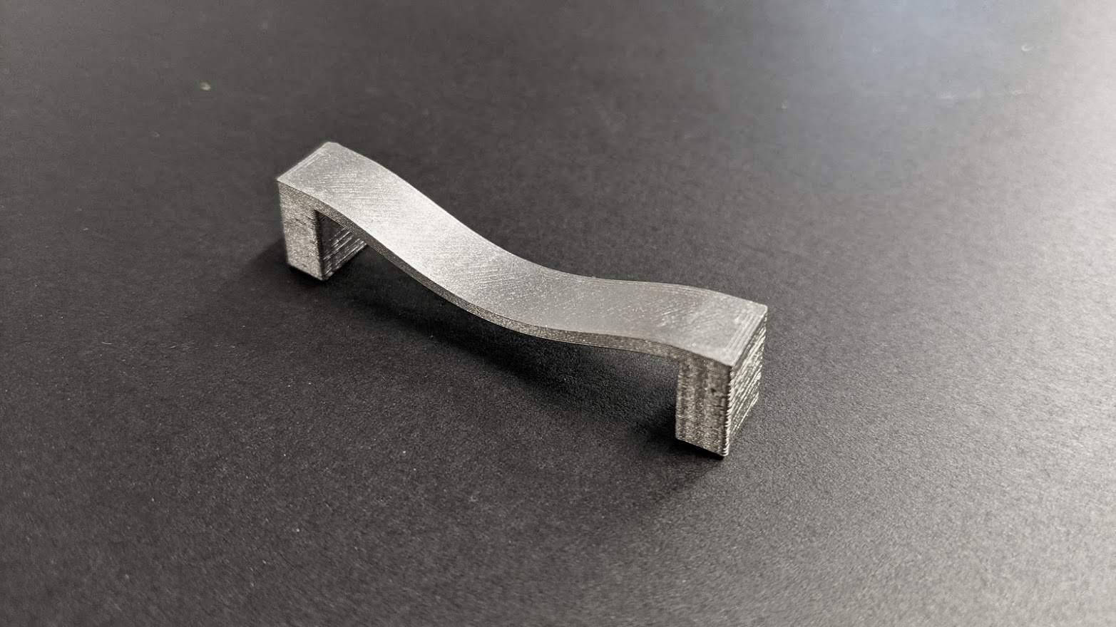
As the material’s stiffness decreases while the temperature approaches its melting point, thin, unsupported members or overhanging features lose their ability to support their own mass. This is especially apparent in features with high length:thickness aspect ratios. To prevent this distortion, the Rapidia printer can build up metal feedstock underneath the thin sections and separate it from the part using a thin layer of support material. This metal support prevents the section from drooping, yet remains separable from the section after sintering is complete. With the metal support in place, the thin part section can only sag a distance equal to the thickness of the support layer, which will burn away earlier in sintering.

An unsupported span after sagging during sintering (printed as a straight bridge).
¶ Drag
Collapsing of the free space between individual metal particles as they coalesce during sintering corresponds to a reduction of the part’s size. Typical shrinkage for 3D printed bound metal parts is in the range of 10-20% in linear dimensions.
At the interface between the part and the sintering surface, there is inevitably some friction which resists this shrinkage; parts that do not provide enough shrinkage force across their base will shrink unevenly in the horizontal plane. Such parts include those with delicate features or open sections in contact with the furnace setter plate.
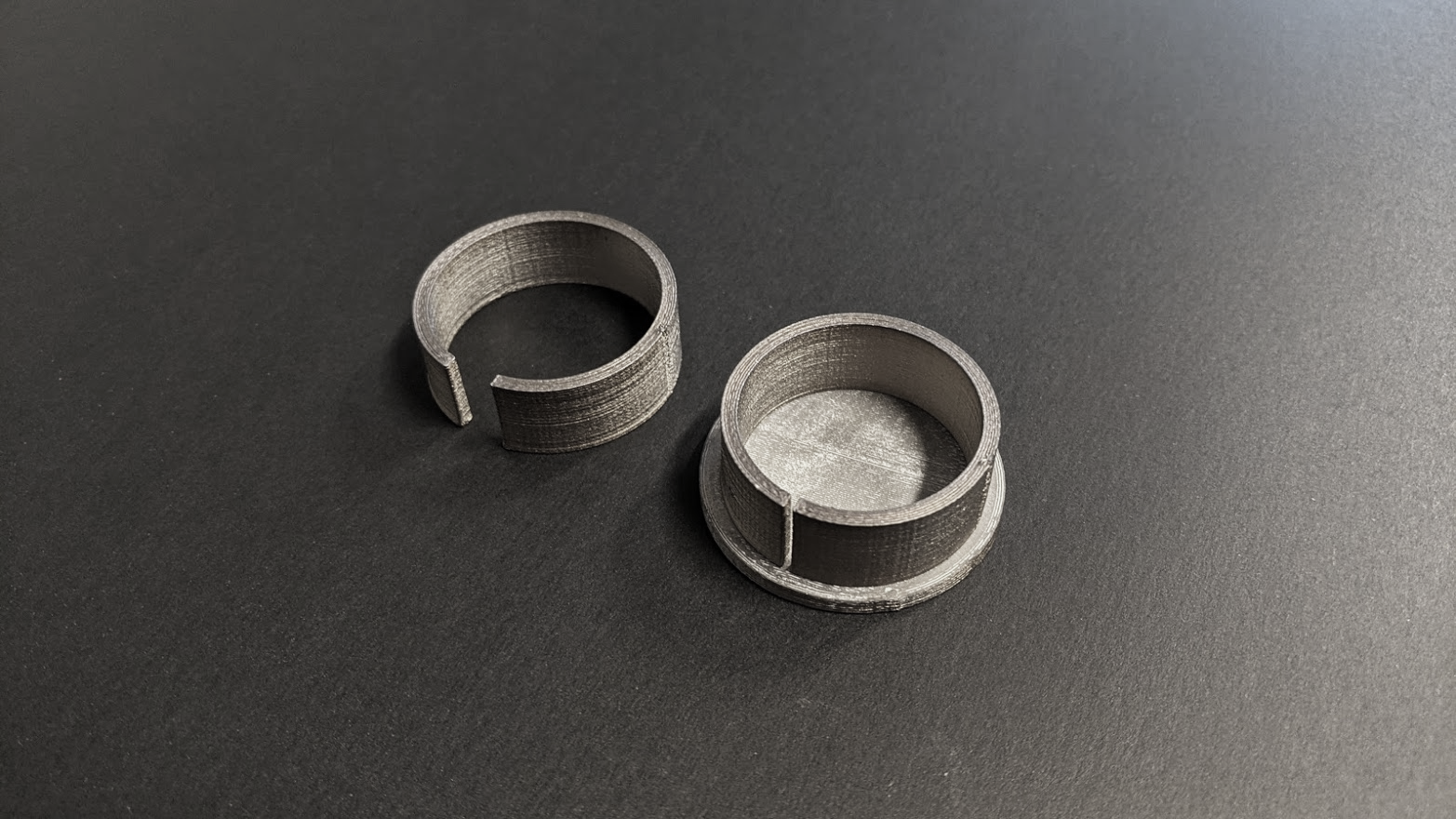
The best way to minimize this distortion is to print the part on a “raft”—a slab of metal feedstock which provides even shrinkage across the part and a buffer from the stationary sintering surface. Where the part touches the raft, a thin separation layer of support material is used to prevent the raft and the part from sintering together.

Two split rings printed to the same dimensions, one sintered on a raft. Notice that the part not sintered on a raft “opened up” and lost its circularity.
¶ Mold Lock
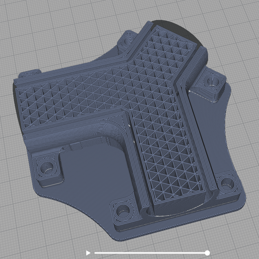
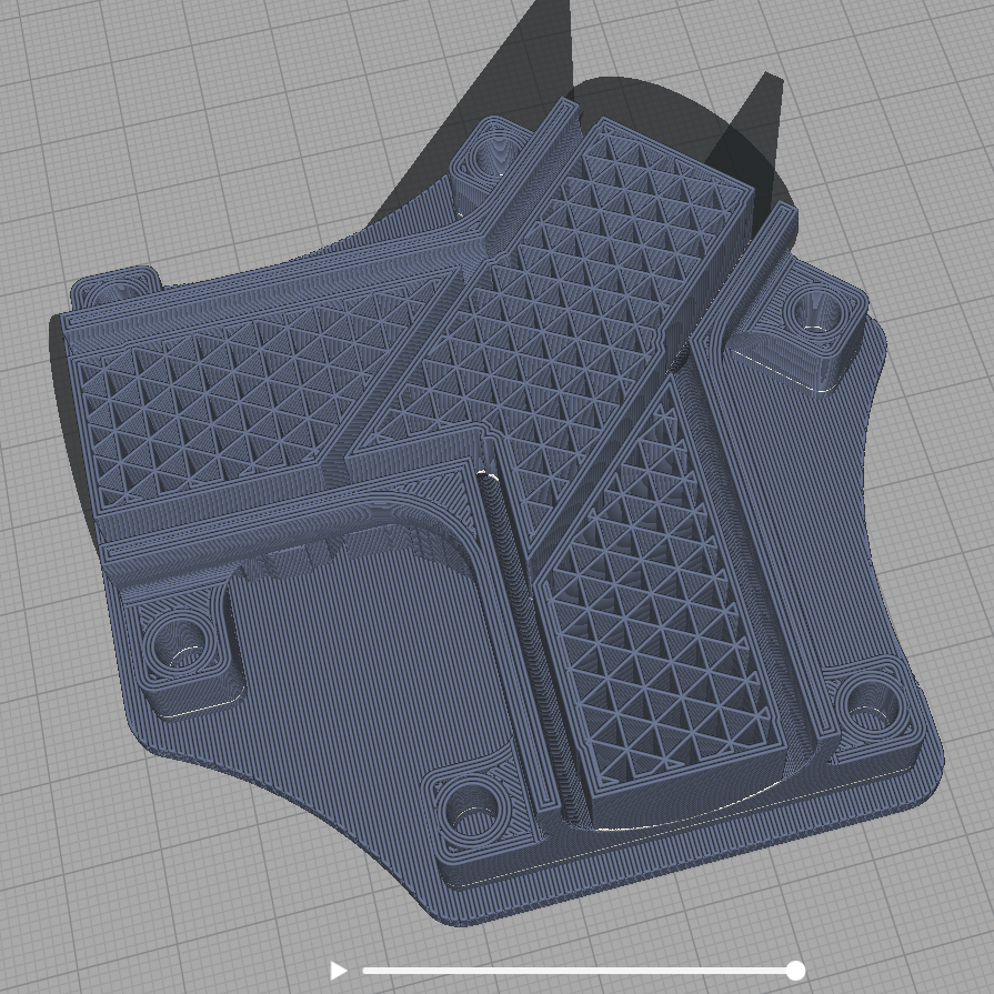
The best way to plan internal metal support geometries is to think about easiest ways to remove the metal support and respective access points for tooling. In the picture below you see that a three way tube has been filled with metal support to avoid sagging, but was not calculated for sufficient removal of the material. Sectioned in three parts that can be removed from each side with some space for tooling would be a better approach.
Further, make sure to include an interface layer of evaporative support material to avoid fusion of metal support and main part.

Notice that internal metal support will lock within and cannot be removed after sintering.

Notice how all three parts will easily be removable by sectioning and allowing for margins to insert tooling.